
Arduino UNO-Based Automated Rain Detection and Motor Control System
View and Edit Project In Cirkit Designer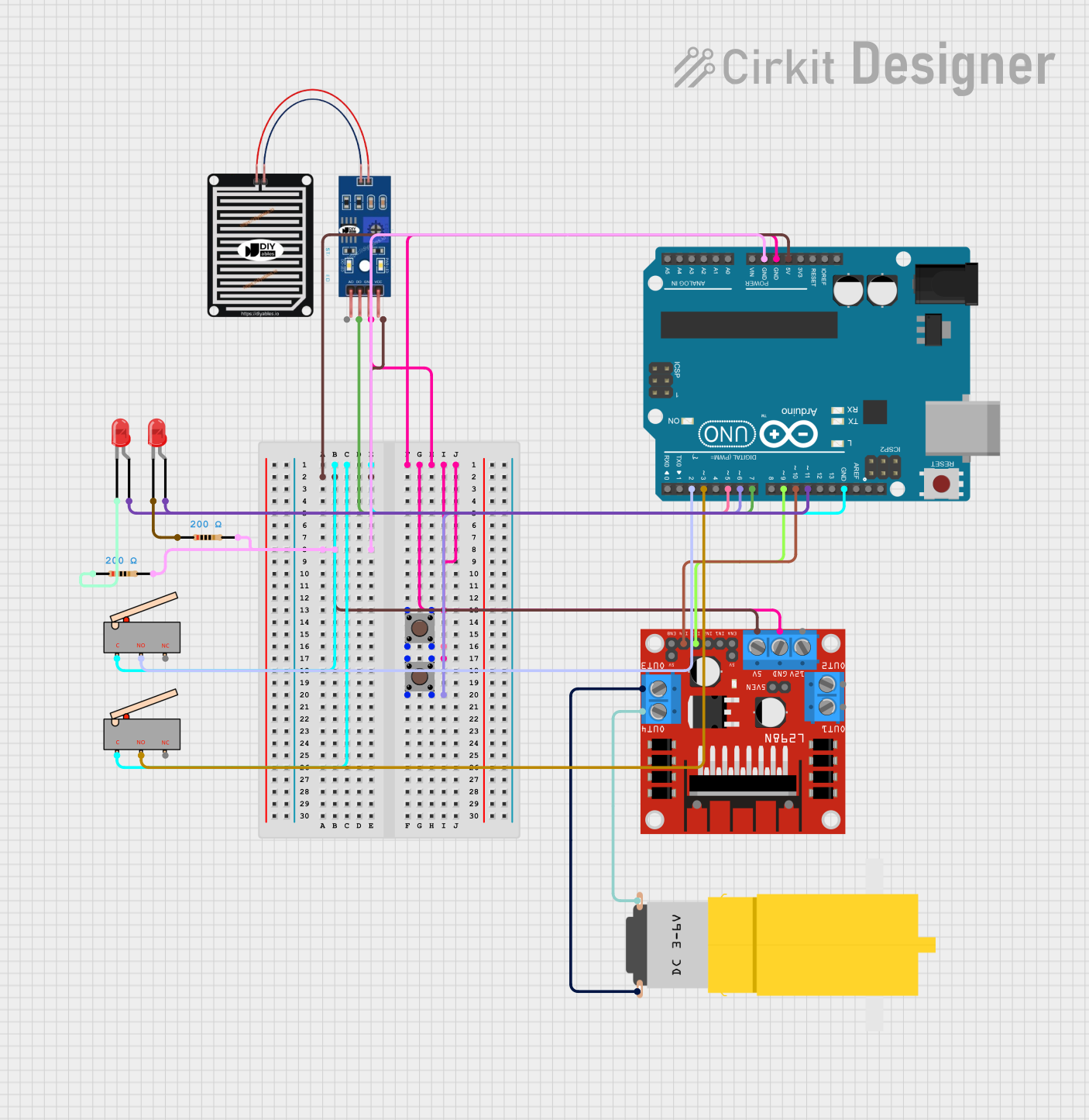
Circuit Documentation
Summary
This document provides a detailed overview of a circuit that includes an Arduino UNO microcontroller, a DC motor driver, a hobby motor, a rain sensor, LEDs, limit switches, pushbuttons, and resistors. The circuit is designed to control a motor and respond to environmental inputs such as rain and button presses, with visual feedback provided by LEDs.
Component List
Arduino UNO
- Description: Microcontroller board based on the ATmega328P.
- Pins: UNUSED, IOREF, Reset, 3.3V, 5V, GND, Vin, A0, A1, A2, A3, A4, A5, SCL, SDA, AREF, D13, D12, D11, D10, D9, D8, D7, D6, D5, D4, D3, D2, D1, D0
L298N DC Motor Driver
- Description: Dual H-Bridge motor driver.
- Pins: OUT1, OUT2, 12V, GND, 5V, OUT3, OUT4, 5V-ENA-JMP-I, 5V-ENA-JMP-O, +5V-J1, +5V-J2, ENA, IN1, IN2, IN3, IN4, ENB
Motor (Hobby)
- Description: Yellow geared DC motor.
- Pins: vcc, GND
Rain Sensor
- Description: Sensor to detect rain.
- Pins: AO, DO, GRD, VCC
LED: Two Pin (Red)
- Description: Red LED.
- Pins: cathode, anode
Limit Switch
- Description: Mechanical switch to detect physical limits.
- Pins: C, NO, NC
Pushbutton
- Description: Simple pushbutton switch.
- Pins: Pin 3 (out), Pin 4 (out), Pin 1 (in), Pin 2 (in)
Resistor
- Description: 200 Ohm resistor.
- Pins: pin1, pin2
- Properties: Resistance: 200 Ohms
Wiring Details
Arduino UNO
GND is connected to:
- Limit switch (C)
- Limit switch (C)
- Pushbutton (Pin 3 (out))
- Pushbutton (Pin 1 (in))
- Pushbutton (Pin 3 (out))
- Pushbutton (Pin 1 (in))
- Rain Sensor (GRD)
- L298N DC motor driver (GND)
- Resistor (pin2)
- Resistor (pin2)
5V is connected to:
- Rain Sensor (VCC)
- L298N DC motor driver (5V)
D5 is connected to:
- Pushbutton (Pin 4 (out))
- Pushbutton (Pin 2 (in))
D6 is connected to:
- Pushbutton (Pin 4 (out))
- Pushbutton (Pin 2 (in))
D11 is connected to:
- LED: Two Pin (red) (anode)
- LED: Two Pin (red) (anode)
D10 is connected to:
- L298N DC motor driver (IN4)
D9 is connected to:
- L298N DC motor driver (IN3)
D7 is connected to:
- Rain Sensor (DO)
D3 is connected to:
- Limit switch (NO)
D2 is connected to:
- Limit switch (NO)
L298N DC Motor Driver
OUT3 is connected to:
- Motor (GND)
OUT4 is connected to:
- Motor (vcc)
LED: Two Pin (Red)
- cathode is connected to:
- Resistor (pin1)
Resistor
- pin2 is connected to:
- Arduino UNO (GND)
Documented Code
Arduino UNO Code
void setup() {
  // put your setup code here, to run once:

}

void loop() {
  // put your main code here, to run repeatedly:

}
This code is a basic template for the Arduino UNO, with setup and loop functions defined but not yet implemented. The setup function runs once when the microcontroller is powered on or reset, and the loop function runs continuously after the setup function completes.