
Arduino UNO-Based IoT Indoor Air Quality Monitoring System with Wi-Fi and LCD Display
View and Edit Project In Cirkit Designer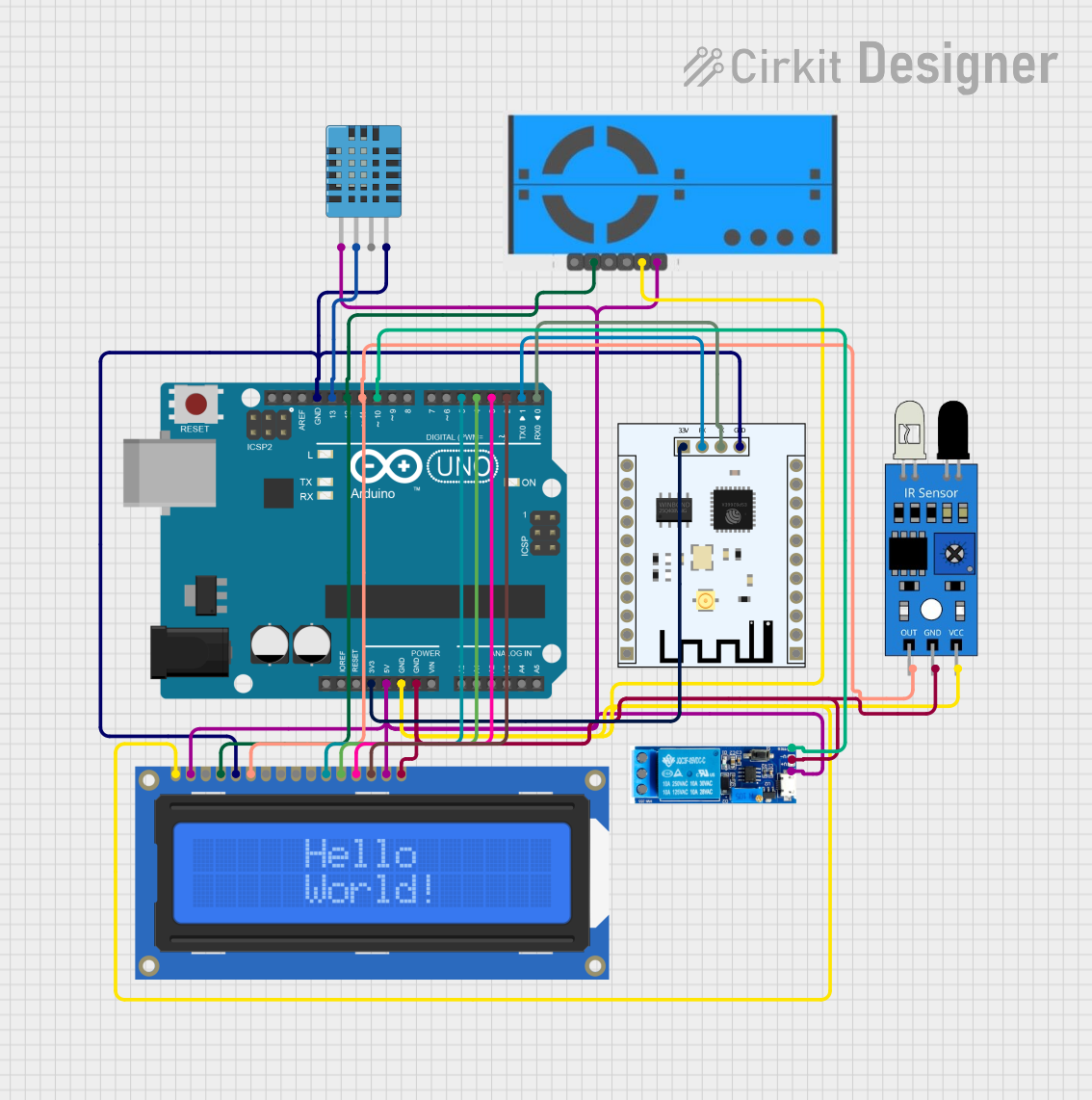
Circuit Documentation
Summary
The Integrated Humidity, Infrared, and Particulates (IHIP) System is an Internet of Things (IoT) based indoor air quality monitoring and controlling system. This circuit reads data from a DHT11 sensor, an IR sensor, and a PM2.5 air quality sensor. The data is displayed on an LCD and sent to an ESP8266 WiFi module for IoT-based monitoring. Additionally, the system controls a relay based on the sensor readings.
Component List
Arduino UNO
- Description: Microcontroller board based on the ATmega328P.
- Pins: UNUSED, IOREF, Reset, 3.3V, 5V, GND, Vin, A0, A1, A2, A3, A4, A5, SCL, SDA, AREF, D13, D12, D11, D10, D9, D8, D7, D6, D5, D4, D3, D2, D1, D0
DHT11 Humidity and Temperature Sensor
- Description: Sensor for measuring humidity and temperature.
- Pins: VDD, DATA, NULL, GND
PM2.5 Air Quality Sensor and Breadboard Adapter Kit - PMS5003
- Description: Sensor for measuring particulate matter (PM2.5) in the air.
- Pins: VCC, GND, SET, RX, TX, RST
IR Sensor
- Description: Infrared sensor for detecting objects.
- Pins: out, gnd, vcc
ESP8266 ESP-201 WiFi Module
- Description: WiFi module for IoT applications.
- Pins: 3.3V, IO4, D3, D1, D0, CMD, CLK, D2, IO2, IO0, GND, IO5, T_OUT, RST, CHIP_EN, XPD, IO14, IO12, IO13, IO15, RX, TX
Relay Module 5V-30V
- Description: Relay module for switching high voltage devices.
- Pins: common contact, normally open, normally closed, trigger, V-, V+
Adafruit Standard LCD 16x2 White on Blue
- Description: 16x2 character LCD display.
- Pins: VSS, VDD, V0, RS, R/W, E, DB0, DB1, DB2, DB3, DB4, DB5, DB6, DB7, LED+, LED-
Wiring Details
Arduino UNO
- 3.3V: Connected to 3.3V of ESP8266 ESP-201 WiFi Module
- 5V: Connected to VDD of DHT11, V+ of Relay Module, VDD and LED+ of Adafruit LCD, VCC of PM2.5 Sensor
- GND: Connected to GND of PM2.5 Sensor, VSS of Adafruit LCD, vcc of IR Sensor, V- of Relay Module, LED- of Adafruit LCD, GND of DHT11, GND of ESP8266
- D13: Connected to DATA of DHT11
- D12: Connected to RS of Adafruit LCD, TX of PM2.5 Sensor
- D11: Connected to E of Adafruit LCD, out of IR Sensor
- D10: Connected to trigger of Relay Module
- D5: Connected to DB4 of Adafruit LCD
- D4: Connected to DB5 of Adafruit LCD
- D3: Connected to DB6 of Adafruit LCD
- D2: Connected to DB7 of Adafruit LCD
- D1: Connected to RX of ESP8266
- D0: Connected to TX of ESP8266
DHT11 Humidity and Temperature Sensor
- VDD: Connected to 5V of Arduino UNO
- DATA: Connected to D13 of Arduino UNO
- GND: Connected to GND of Arduino UNO
PM2.5 Air Quality Sensor and Breadboard Adapter Kit - PMS5003
- VCC: Connected to 5V of Arduino UNO
- GND: Connected to GND of Arduino UNO
- TX: Connected to D12 of Arduino UNO
IR Sensor
- out: Connected to D11 of Arduino UNO
- gnd: Connected to GND of Arduino UNO
- vcc: Connected to GND of Arduino UNO
ESP8266 ESP-201 WiFi Module
- 3.3V: Connected to 3.3V of Arduino UNO
- GND: Connected to GND of Arduino UNO
- RX: Connected to D1 of Arduino UNO
- TX: Connected to D0 of Arduino UNO
Relay Module 5V-30V
- V+: Connected to 5V of Arduino UNO
- V-: Connected to GND of Arduino UNO
- trigger: Connected to D10 of Arduino UNO
Adafruit Standard LCD 16x2 White on Blue
- VDD: Connected to 5V of Arduino UNO
- VSS: Connected to GND of Arduino UNO
- LED+: Connected to 5V of Arduino UNO
- LED-: Connected to GND of Arduino UNO
- RS: Connected to D12 of Arduino UNO
- E: Connected to D11 of Arduino UNO
- DB4: Connected to D5 of Arduino UNO
- DB5: Connected to D4 of Arduino UNO
- DB6: Connected to D3 of Arduino UNO
- DB7: Connected to D2 of Arduino UNO
Code Documentation
/*
 * IHIP (Integrated Humidity, Infrared, and Particulates System)
 * Internet of Things (IoT) - based Indoor Air Quality Monitoring and Controlling
 *
 * This Arduino sketch reads data from a DHT11 sensor, an IR sensor, and a PM2.5
 * air quality sensor. It displays the data on an LCD and sends it to an ESP8266
 * WiFi module for IoT-based monitoring. Additionally, it controls a relay based
 * on the sensor readings.
 */

#include <DHT.h>
#include <LiquidCrystal.h>

// Pin definitions
#define DHTPIN 13
#define DHTTYPE DHT11
#define IRPIN 11
#define RELAYPIN 10
#define LCD_RS 12
#define LCD_E 11
#define LCD_D4 5
#define LCD_D5 4
#define LCD_D6 3
#define LCD_D7 2

// Initialize DHT sensor
DHT dht(DHTPIN, DHTTYPE);

// Initialize LCD
LiquidCrystal lcd(LCD_RS, LCD_E, LCD_D4, LCD_D5, LCD_D6, LCD_D7);

void setup() {
  // Start serial communication
  Serial.begin(9600);

  // Initialize DHT sensor
  dht.begin();

  // Initialize LCD
  lcd.begin(16, 2);
  lcd.print("IHIP System");

  // Initialize IR sensor pin
  pinMode(IRPIN, INPUT);

  // Initialize relay pin
  pinMode(RELAYPIN, OUTPUT);
  digitalWrite(RELAYPIN, LOW);
}

void loop() {
  // Read humidity and temperature from DHT11
  float humidity = dht.readHumidity();
  float temperature = dht.readTemperature();

  // Read IR sensor value
  int irValue = digitalRead(IRPIN);

  // Display data on LCD
  lcd.setCursor(0, 1);
  lcd.print("H:");
  lcd.print(humidity);
  lcd.print("% T:");
  lcd.print(temperature);
  lcd.print("C");

  // Send data to ESP8266
  Serial.print("Humidity: ");
  Serial.print(humidity);
  Serial.print("% Temperature: ");
  Serial.print(temperature);
  Serial.print("C IR: ");
  Serial.println(irValue);

  // Control relay based on IR sensor
  if (irValue == HIGH) {
    digitalWrite(RELAYPIN, HIGH);
  } else {
    digitalWrite(RELAYPIN, LOW);
  }

  // Wait for 2 seconds before next loop
  delay(2000);
}
This code initializes the DHT11 sensor, IR sensor, and LCD display. It reads the humidity and temperature from the DHT11 sensor, the IR sensor value, and displays the data on the LCD. The data is also sent to the ESP8266 WiFi module for IoT-based monitoring. The relay is controlled based on the IR sensor readings.