Arduino UNO Based Ambient Light Monitoring with I2C LCD Display
Circuit Documentation
Summary
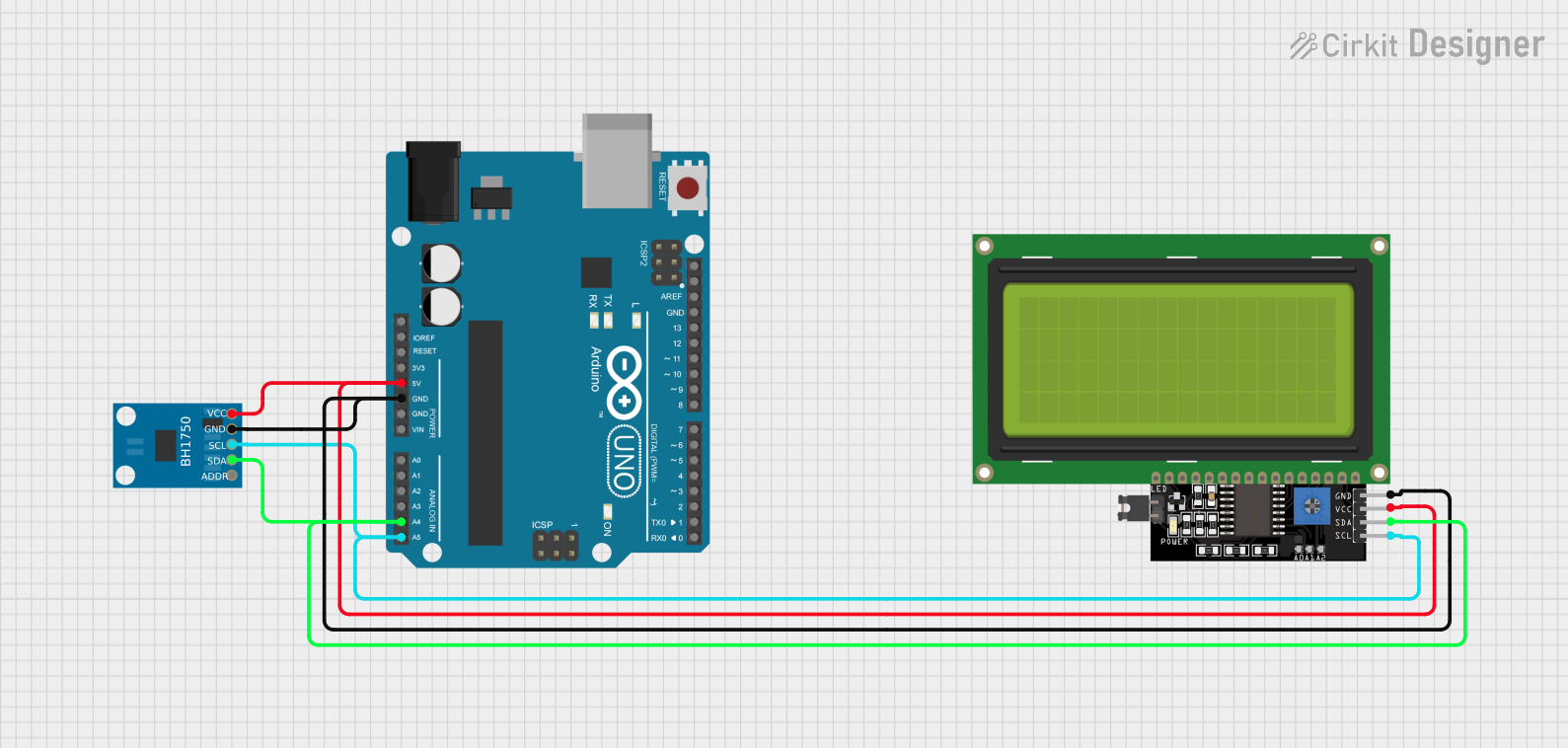
This circuit integrates an Arduino UNO microcontroller with a BH1750 light sensor and a 20x4 LCD display with I2C interface. The purpose of the circuit is to measure ambient light intensity using the BH1750 sensor and display the readings in lux on the LCD. The Arduino UNO serves as the central processing unit, reading sensor data and controlling the LCD output. The components are interconnected via I2C communication protocol, which allows for a simplified two-wire connection (SCL for clock and SDA for data) between the devices.
Component List
Arduino UNO
- Description: A microcontroller board based on the ATmega328P.
- Pins Used: 5V, GND, A4 (SDA), A5 (SCL), and other digital and analog pins for various functions.
BH1750 Light Sensor
- Description: A digital ambient light sensor capable of direct I2C communication.
- Pins Used: VCC, GND, SCL, SDA.
LCD Display 20x4 I2C
- Description: A 20x4 character LCD display with an I2C interface module.
- Pins Used: SCL, SDA, VCC, GND.
Wiring Details
Arduino UNO
- 5V to VCC on BH1750 and LCD Display 20x4 I2C.
- GND to GND on BH1750 and LCD Display 20x4 I2C.
- A4 (SDA) to SDA on BH1750 and LCD Display 20x4 I2C.
- A5 (SCL) to SCL on BH1750 and LCD Display 20x4 I2C.
BH1750 Light Sensor
- VCC connected to 5V on Arduino UNO.
- GND connected to GND on Arduino UNO.
- SCL connected to A5 (SCL) on Arduino UNO.
- SDA connected to A4 (SDA) on Arduino UNO.
LCD Display 20x4 I2C
- VCC connected to 5V on Arduino UNO.
- GND connected to GND on Arduino UNO.
- SCL connected to A5 (SCL) on Arduino UNO.
- SDA connected to A4 (SDA) on Arduino UNO.
Documented Code
Arduino UNO Code
#include <BH1750.h>
#include <Wire.h>
#include <LiquidCrystal_I2C.h>

LiquidCrystal_I2C lcd(0x27, 20, 4);  // LCD I2C address, 20 columns and 4 rows
BH1750 lightMeter;  // BH1750 light sensor object

void setup() {
  Serial.begin(9600);
  Wire.begin();
  lightMeter.begin();
  Serial.println(F("BH1750 Test begin"));
  lcd.begin();  // Initialize the LCD without arguments
  lcd.backlight();   // Turn on the LCD backlight
}

void loop() {
  float lux = lightMeter.readLightLevel();  // Read light intensity in lux
  Serial.print("Light: ");
  Serial.print(lux);
  Serial.println(" lx");

  lcd.setCursor(0, 0);  // Set cursor at the beginning of the first line
  lcd.print("Lux : ");
  lcd.print(lux);  // Display the lux value on the LCD

  delay(1000);  // Wait for 1 second before taking the next reading
}
This code initializes the I2C communication, sets up the LCD display, and continuously reads the light level from the BH1750 sensor. The light level in lux is printed to the serial monitor and displayed on the LCD. The LCD is initialized with the I2C address 0x27, which may need to be adjusted depending on the hardware. The backlight of the LCD is turned on for visibility. The sensor readings are taken every second, as indicated by the delay(1000) function call.