Arduino UNO Controlled Rain-Activated Servo System
Circuit Documentation
Summary
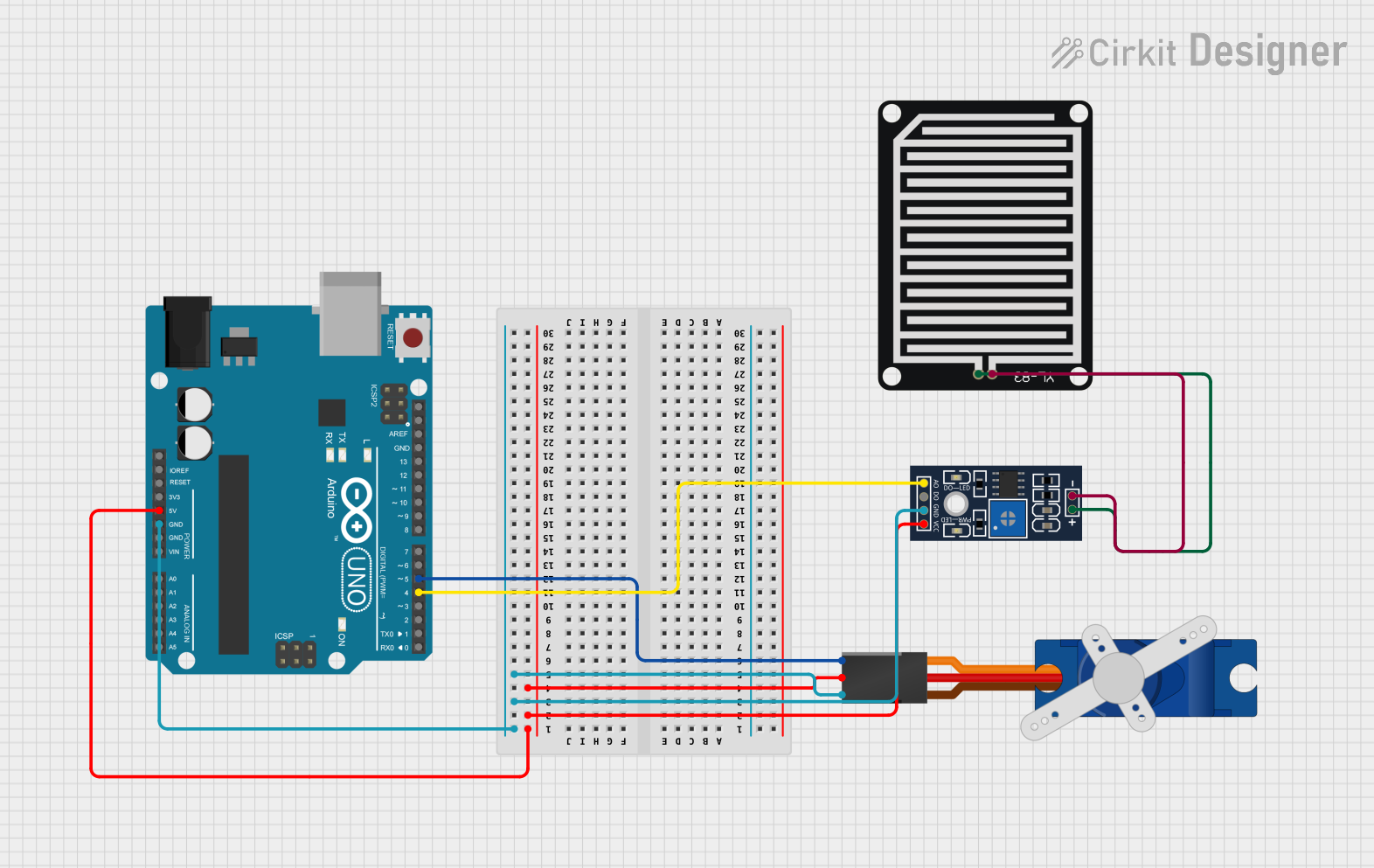
This circuit integrates an Arduino UNO microcontroller with a YL-83 Rain Sensor system and a Tower Pro SG90 servo motor. The Arduino UNO reads the analog output from the rain sensor's control board and controls the servo motor based on the sensor's readings. The servo motor is used to actuate a mechanism, such as opening or closing a tap, in response to the detection of rain.
Component List
Arduino UNO
- Description: A microcontroller board based on the ATmega328P.
- Purpose: Acts as the central processing unit of the circuit, reading sensor data and controlling the servo motor.
YL-83 Rain Sensor - Detection Board
- Description: A board that detects rain by measuring the resistance between two tracks.
- Purpose: Senses the presence of rainwater.
YL-83 Rain Sensor - Control Board
- Description: A board that processes the signal from the detection board and provides digital and analog outputs.
- Purpose: Outputs an analog signal corresponding to the amount of rain detected.
Tower Pro SG90 Servo
- Description: A small and lightweight servo motor capable of precise control.
- Purpose: Actuates a mechanism in response to the rain sensor's output.
Wiring Details
Arduino UNO
- 5V: Powers the YL-83 Rain Sensor - Control Board and the Tower Pro SG90 servo.
- GND: Common ground for the circuit.
- D5: Connected to the signal pin of the Tower Pro SG90 servo to control its position.
- D4: Receives the analog output from the YL-83 Rain Sensor - Control Board.
YL-83 Rain Sensor - Detection Board
- POS: Connected to the negative pin (NEG) of the YL-83 Rain Sensor - Control Board.
- NEG: Connected to the positive pin (POS) of the YL-83 Rain Sensor - Control Board.
YL-83 Rain Sensor - Control Board
- VCC: Powered by the 5V output from the Arduino UNO.
- GND: Connected to the common ground of the circuit.
- AO: Analog output connected to the D4 pin on the Arduino UNO.
- POS: Connected to the NEG pin of the YL-83 Rain Sensor - Detection Board.
- NEG: Connected to the POS pin of the YL-83 Rain Sensor - Detection Board.
Tower Pro SG90 Servo
- Signal: Controlled by the D5 pin on the Arduino UNO.
- +5V: Powered by the 5V output from the Arduino UNO.
- GND: Connected to the common ground of the circuit.
Documented Code
#include <Servo.h>

Servo tap_servo;

int sensor_pin = 4; // Analog input pin connected to the rain sensor
int tap_servo_pin = 5; // Digital output pin connected to the servo signal line
int val; // Variable to store the sensor reading

void setup() {
  pinMode(sensor_pin, INPUT); // Initialize the sensor pin as an input
  tap_servo.attach(tap_servo_pin); // Attach the servo motor to its control pin
}

void loop() {
  val = digitalRead(sensor_pin); // Read the digital value from the rain sensor

  if (val == 0) {
    tap_servo.write(0); // If no rain is detected, set servo to position 0
  }
  if (val == 1) {
    tap_servo.write(180); // If rain is detected, set servo to position 180
  }
}
Filename: sketch.ino
Description: This code snippet is responsible for reading the digital output from the rain sensor and controlling the servo motor accordingly. When the sensor detects rain (represented by a high signal), the servo is set to its 180-degree position. Conversely, when no rain is detected (represented by a low signal), the servo is set to its 0-degree position.