
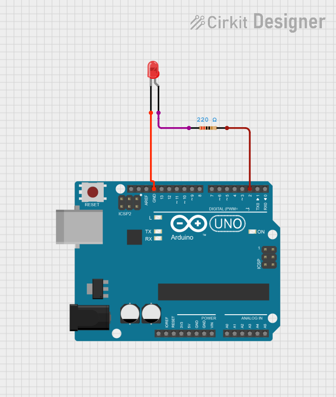
Circuit Documentation
Summary
This circuit is designed to blink an LED using an Arduino UNO. The LED is connected to a digital pin on the Arduino through a current-limiting resistor. The Arduino is programmed to turn the LED on and off at one-second intervals, with status messages printed to the serial monitor.
Component List
Arduino UNO
- Description: A microcontroller board based on the ATmega328P.
- Pins: UNUSED, IOREF, Reset, 3.3V, 5V, GND, Vin, A0, A1, A2, A3, A4, A5, SCL, SDA, AREF, D13, D12, D11, D10, D9, D8, D7, D6, D5, D4, D3, D2, D1, D0
LED: Two Pin (red)
- Description: A red LED with two pins: cathode and anode.
- Pins: cathode, anode
Resistor
- Description: A resistor with a resistance of 220 Ohms.
- Pins: pin1, pin2
- Properties:
- Resistance: 220 Ohms
Wiring Details
Arduino UNO
- GND is connected to the cathode of the LED.
- D2 is connected to pin2 of the resistor.
LED: Two Pin (red)
- cathode is connected to GND of the Arduino UNO.
- anode is connected to pin1 of the resistor.
Resistor
- pin1 is connected to the anode of the LED.
- pin2 is connected to D2 of the Arduino UNO.
Code Documentation
Code for Arduino UNO
void setup() {
  pinMode(2, OUTPUT);
  Serial.begin(9600);
}

void loop()
{
  digitalWrite(2, HIGH);
  delay(1000);
  Serial.println("Led is in ON state");
  digitalWrite(2, LOW);
  delay(1000);
  Serial.println("Led is in off state");
}
Code Explanation:
- setup(): This function runs once when the Arduino is powered on or reset. It sets pin 2 as an output and initializes the serial communication at a baud rate of 9600.
- loop(): This function runs repeatedly. It turns the LED on by setting pin 2 to HIGH, waits for one second, prints "Led is in ON state" to the serial monitor, turns the LED off by setting pin 2 to LOW, waits for another second, and then prints "Led is in off state" to the serial monitor. This cycle repeats indefinitely.