
Arduino Nano and ATtiny-Powered Ultrasonic Distance Measurement System
View and Edit Project In Cirkit Designer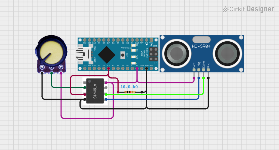
Circuit Documentation
Summary of the Circuit
This circuit integrates an Arduino Nano microcontroller with an HC-SR04 Ultrasonic Sensor, an ATTiny microcontroller, a potentiometer, and a resistor. The Arduino Nano serves as the primary control unit, while the ATTiny is used for additional processing or control tasks. The HC-SR04 sensor is used for distance measurement, and the potentiometer provides an adjustable voltage input. The resistor is used to form a voltage divider or to limit current in the circuit.
Component List
Arduino Nano
- Description: A compact microcontroller board based on the ATmega328P.
- Pins: D1/TX, D0/RX, RESET, GND, D2, D3, D4, D5, D6, D7, D8, D9, D10, D11/MOSI, D12/MISO, VIN, 5V, A7, A6, A5, A4, A3, A2, A1, A0, AREF, 3V3, D13/SCK.
ATTiny Microcontroller
- Description: A small, low-power CMOS 8-bit microcontroller based on the AVR enhanced RISC architecture.
- Pins: PB5, PB3, PB4, GND, PB0, PB1, PB2, VCC.
HC-SR04 Ultrasonic Sensor
- Description: An ultrasonic distance sensor capable of measuring distances from 2cm to 400cm.
- Pins: VCC, TRIG, ECHO, GND.
Potentiometer
- Description: A three-terminal resistor with a sliding or rotating contact that forms an adjustable voltage divider.
- Pins: GND, Output, VCC.
Resistor
- Description: A passive two-terminal electrical component that implements electrical resistance as a circuit element.
- Resistance: 10,000 Ohms.
- Pins: pin1, pin2.
Wiring Details
Arduino Nano
- GND: Connected to the common ground net.
- 5V: Connected to the VCC net, providing power to other components.
- A2: Connected to the resistor and ATTiny PB4.
ATTiny Microcontroller
- GND: Connected to the common ground net.
- VCC: Connected to the VCC net, receiving power from the Arduino Nano 5V pin.
- PB4: Connected to the Arduino Nano A2 pin and one end of the resistor.
- PB3: Connected to the potentiometer output.
- PB0: Connected to the HC-SR04 TRIG pin.
- PB1: Connected to the HC-SR04 ECHO pin.
HC-SR04 Ultrasonic Sensor
- VCC: Connected to the VCC net.
- TRIG: Connected to the ATTiny PB0 pin.
- ECHO: Connected to the ATTiny PB1 pin.
- GND: Connected to the common ground net.
Potentiometer
- GND: Connected to the common ground net.
- Output: Connected to the ATTiny PB3 pin.
- VCC: Connected to the VCC net.
Resistor
- pin1: Connected to the Arduino Nano A2 pin and ATTiny PB4.
- pin2: Connected to the common ground net.
Documented Code
Arduino Nano Code (sketch.ino)
void setup() {
  // put your setup code here, to run once:

}

void loop() {
  // put your main code here, to run repeatedly:

}
ATTiny Microcontroller Code
No code provided for the ATTiny microcontroller.
This documentation provides an overview of the circuit, including the purpose and connection details of each component, as well as the code for the Arduino Nano. The ATTiny microcontroller code is not included in the provided inputs and should be added when available.