
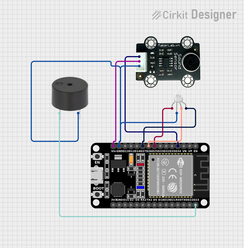
Circuit Documentation
Summary
The circuit in question is designed to interface an ESP32 microcontroller with a sound sensor, an RGB LED, and a buzzer. The ESP32 is a versatile microcontroller with a wide range of GPIO pins, which are used here to receive signals from the sound sensor, control the RGB LED, and drive the buzzer. The sound sensor detects noise levels and sends a signal to the ESP32 for processing. The RGB LED is used to visually represent the output or status, and the buzzer can provide audible feedback. The circuit is powered through the ESP32, which distributes power to the other components.
Component List
ESP32 (30 pin)
- Description: A microcontroller with Wi-Fi and Bluetooth capabilities, featuring a wide range of GPIO pins.
- Purpose: Acts as the central processing unit of the circuit, reading sensor data, controlling the RGB LED, and driving the buzzer.
MKE-S06 Sound Sensor
- Description: A sound detection module capable of sensing the intensity of sound in the environment.
- Purpose: Provides sound level input to the ESP32 for further processing.
Buzzer
- Description: An electromechanical component that emits sound when powered.
- Purpose: Used to generate audible alerts or feedback based on the ESP32's logic.
RGB LED (Wokwi compatible)
- Description: A light-emitting diode that can display multiple colors by mixing red, green, and blue.
- Purpose: Serves as a visual indicator controlled by the ESP32.
Wiring Details
ESP32 (30 pin)
- EN: Not connected in this circuit.
- VP: Not connected in this circuit.
- VN: Not connected in this circuit.
- D34: Connected to the SIG pin of the MKE-S06 Sound Sensor.
- D25: Connected to the R pin of the RGB LED.
- D26: Connected to the G pin of the RGB LED.
- D27: Connected to the B pin of the RGB LED.
- GND: Common ground, connected to the GND pins of the MKE-S06 Sound Sensor, RGB LED, and buzzer.
- Vin: Power input, connected to the 5V pin of the MKE-S06 Sound Sensor.
- D23: Connected to the PIN of the buzzer.
MKE-S06 Sound Sensor
- SIG: Connected to the D34 pin of the ESP32.
- 5V: Connected to the Vin pin of the ESP32.
- GND: Connected to the GND pin of the ESP32.
Buzzer
- PIN: Connected to the D23 pin of the ESP32.
- GND: Connected to the GND pin of the ESP32.
RGB LED (Wokwi compatible)
- R: Connected to the D25 pin of the ESP32.
- G: Connected to the D26 pin of the ESP32.
- B: Connected to the D27 pin of the ESP32.
- COM: Connected to the GND pin of the ESP32.
Documented Code
No code has been provided for the microcontroller. The documentation of the code would typically include a description of the functionality, setup, and loop routines, along with any functions or libraries used to control the components in the circuit. Since no code is available, this section cannot be completed.