
Arduino Nano Controlled Robot with Dual IR Sensors and L293D Motor Driver
View and Edit Project In Cirkit Designer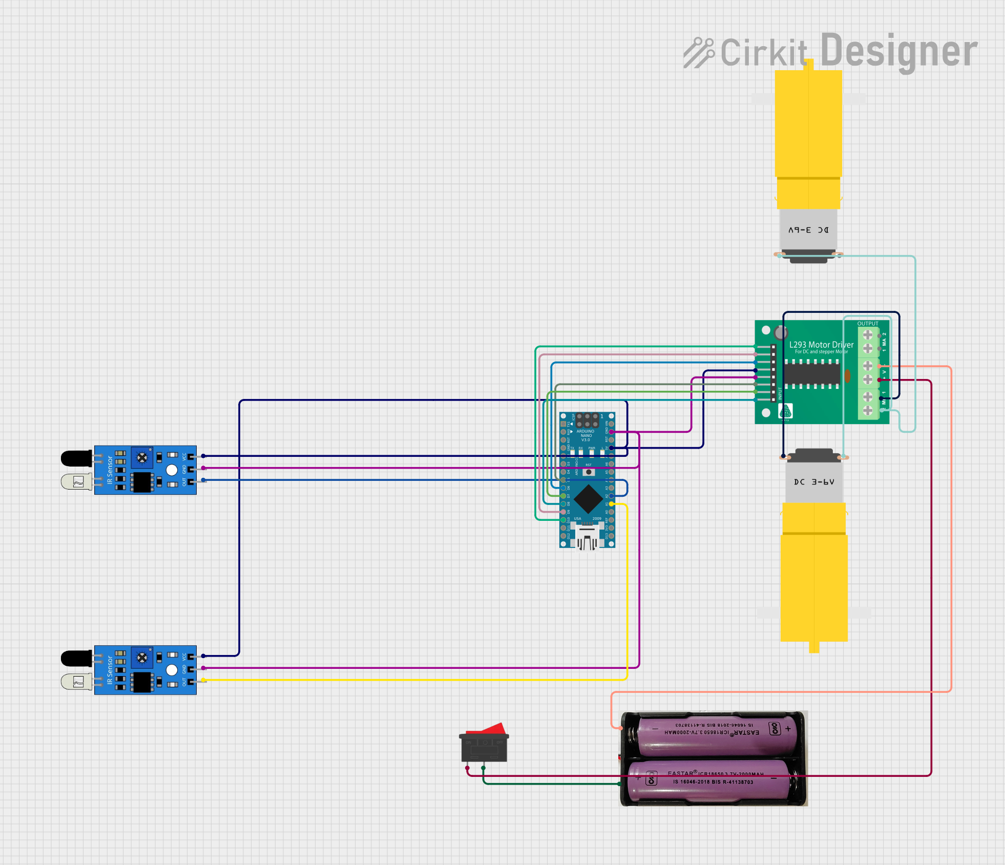
Circuit Documentation
Summary
This document provides a detailed overview of a circuit that includes an Arduino Nano microcontroller, an L293D motor driver, two IR sensors, a rocker switch, a 7.4V power source, and two hobby motors. The circuit is designed to control the motors using signals from the Arduino Nano, which are modulated based on inputs from the IR sensors. The L293D motor driver interfaces between the Arduino and the motors, allowing for control of the motor direction and speed. The rocker switch is used to control the power supply to the motor driver, and the 7.4V power source provides the necessary voltage for the motors and the motor driver.
Component List
Arduino Nano
- Microcontroller board based on the ATmega328P
- Pins: D1/TX, D0/RX, RESET, GND, D2 to D13, VIN, 5V, A0 to A7, AREF, 3V3
L293D Motor Driver
- Motor driver IC capable of driving two motors
- Pins: B1, B2, A1, EN_B, EN_A, A2, GND, VCC, +, -, MPIN_1 to MPIN_4
7.4V Power Source
- Power source providing 7.4 volts
- Pins: +, -
IR Sensor (x2)
- Infrared sensor for detecting proximity or line tracking
- Pins: out, gnd, vcc
Rocker Switch
- Switch to control the connection of the power source
- Pins: 1, 2
Motor Amarillo Motorreductor Hobby (x2)
- Yellow geared hobby motor
- Pins: vcc, GND
Wiring Details
Arduino Nano
- D5 connected to L293D Motor Driver EN_B
- D6 connected to L293D Motor Driver EN_A
- D7 connected to L293D Motor Driver B2
- D8 connected to L293D Motor Driver B1
- D9 connected to L293D Motor Driver A2
- D10 connected to L293D Motor Driver A1
- GND connected to IR Sensor GND (both sensors) and L293D Motor Driver GND
- 5V connected to IR Sensor VCC (both sensors) and L293D Motor Driver VCC
- A2 connected to IR Sensor out (sensor 1)
- A1 connected to IR Sensor out (sensor 2)
L293D Motor Driver
- EN_B connected to Arduino Nano D5
- EN_A connected to Arduino Nano D6
- B2 connected to Arduino Nano D7
- B1 connected to Arduino Nano D8
- A2 connected to Arduino Nano D9
- A1 connected to Arduino Nano D10
- GND connected to Arduino Nano GND and IR Sensor GND (both sensors)
- VCC connected to Arduino Nano 5V and IR Sensor VCC (both sensors)
-
- connected to Rocker Switch 1
-
- connected to 7.4V Power Source -
- MPIN_1 connected to Motor Amarillo Motorreductor Hobby vcc (motor 1)
- MPIN_2 connected to Motor Amarillo Motorreductor Hobby GND (motor 1)
7.4V Power Source
-
- connected to Rocker Switch 2
-
- connected to L293D Motor Driver -
IR Sensor (x2)
- out (sensor 1) connected to Arduino Nano A2
- out (sensor 2) connected to Arduino Nano A1
- gnd connected to Arduino Nano GND and L293D Motor Driver GND
- vcc connected to Arduino Nano 5V and L293D Motor Driver VCC
Rocker Switch
- 1 connected to L293D Motor Driver +
- 2 connected to 7.4V Power Source +
Motor Amarillo Motorreductor Hobby (x2)
- vcc (motor 1) connected to L293D Motor Driver MPIN_1
- GND (motor 1) connected to L293D Motor Driver MPIN_2
- vcc (motor 2) connected to L293D Motor Driver MPIN_3 (not listed in the net list, assuming it's a missing connection)
- GND (motor 2) connected to L293D Motor Driver MPIN_4 (not listed in the net list, assuming it's a missing connection)
Documented Code
Arduino Nano Code (sketch.ino)
void setup() {
  // put your setup code here, to run once:

}

void loop() {
  // put your main code here, to run repeatedly:

}
Note: The provided code is a template and does not contain any functional code to control the circuit. The user must implement the setup and loop functions to initialize the pins and define the behavior of the circuit.