
Arduino Nano Light-Activated Motor Controller with L298N Driver and Photocell
View and Edit Project In Cirkit Designer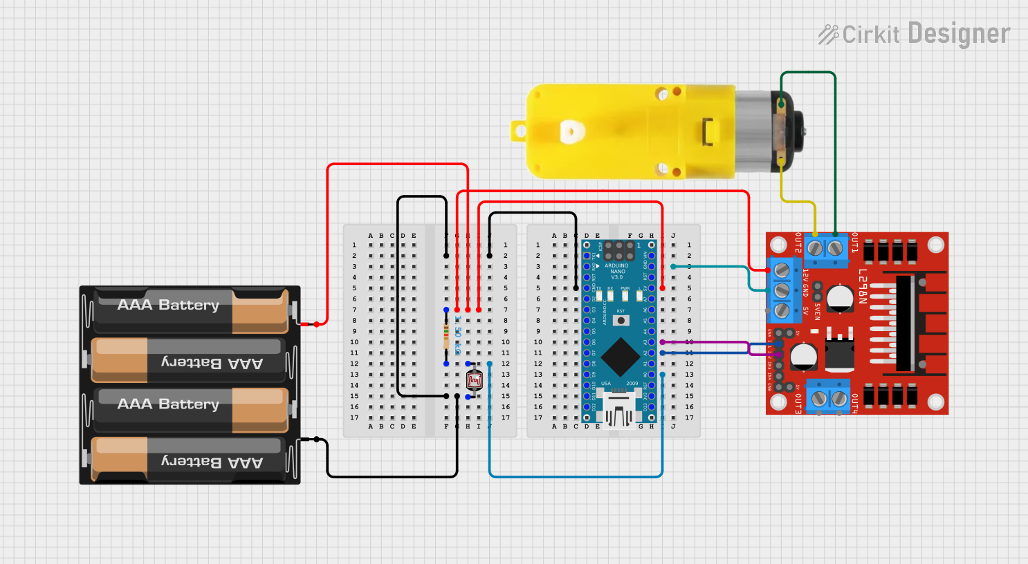
Circuit Documentation
Summary
This circuit is designed to control a motor using an Arduino Nano and an L298N DC motor driver. The motor is activated based on the light intensity detected by a photocell (LDR). The circuit is powered by a 4 x AAA battery mount. The Arduino Nano reads the light intensity from the LDR and controls the motor driver to turn the motor on or off.
Component List
Arduino Nano
- Description: A small, complete, and breadboard-friendly board based on the ATmega328P.
- Pins: D1/TX, D0/RX, RESET, GND, D2, D3, D4, D5, D6, D7, D8, D9, D10, D11/MOSI, D12/MISO, VIN, 5V, A7, A6, A5, A4, A3, A2, A1, A0, AREF, 3V3, D13/SCK
L298N DC Motor Driver
- Description: A high voltage, high current dual full-bridge driver designed to accept standard TTL logic levels and drive inductive loads such as relays, solenoids, DC and stepping motors.
- Pins: OUT1, OUT2, 12V, GND, 5V, OUT3, OUT4, 5V-ENA-JMP-I, 5V-ENA-JMP-O, +5V-J1, +5V-J2, ENA, IN1, IN2, IN3, IN4, ENB
Motor with Reducer
- Description: A DC motor with a gear reducer to provide higher torque.
- Pins: 3 - 6 VCC, GND
Photocell (LDR)
- Description: A light-dependent resistor that changes its resistance based on the light intensity.
- Pins: pin 0, pin 1
4 x AAA Battery Mount
- Description: A battery holder for four AAA batteries to provide power to the circuit.
- Pins: -, +
Resistor
- Description: A 1500 Ohms resistor used to limit current.
- Pins: pin1, pin2
- Properties: Resistance: 1500 Ohms
Wiring Details
Arduino Nano
GND is connected to:
- GND of L298N DC motor driver
- pin 1 of Photocell (LDR)
-
- of 4 x AAA Battery Mount
5V is connected to:
- pin1 of Resistor
- 12V of L298N DC motor driver
-
- of 4 x AAA Battery Mount
A3 is connected to IN2 of L298N DC motor driver
A2 is connected to IN1 of L298N DC motor driver
A0 is connected to:
- pin 0 of Photocell (LDR)
- pin2 of Resistor
L298N DC Motor Driver
GND is connected to GND of Arduino Nano
12V is connected to:
- pin1 of Resistor
- 5V of Arduino Nano
-
- of 4 x AAA Battery Mount
IN2 is connected to A3 of Arduino Nano
IN1 is connected to A2 of Arduino Nano
OUT1 is connected to 3 - 6 VCC of Motor with Reducer
OUT2 is connected to GND of Motor with Reducer
Motor with Reducer
3 - 6 VCC is connected to OUT1 of L298N DC motor driver
GND is connected to OUT2 of L298N DC motor driver
Photocell (LDR)
pin 0 is connected to:
- A0 of Arduino Nano
- pin2 of Resistor
pin 1 is connected to:
- GND of Arduino Nano
-
- of 4 x AAA Battery Mount
4 x AAA Battery Mount
- is connected to:
- GND of Arduino Nano
- pin 1 of Photocell (LDR)
+ is connected to:
- 5V of Arduino Nano
- pin1 of Resistor
- 12V of L298N DC motor driver
Resistor
pin1 is connected to:
- 5V of Arduino Nano
- 12V of L298N DC motor driver
-
- of 4 x AAA Battery Mount
pin2 is connected to:
- A0 of Arduino Nano
- pin 0 of Photocell (LDR)
Code Documentation
int LDR;                     // 儲存光敏電阻的數值
const byte In1 = A2;         // L298N 的 IN1 連接到 NANO 的 A2 腳位
const byte In2 = A3;         // L298N 的 IN2 連接到 NANO 的 A3 腳位

void setup() {
  pinMode(A0, INPUT);        // 設定 A0 為輸入腳位,用來讀取光敏電阻
  pinMode(In1, OUTPUT);      // 設定 In1 為輸出腳位
  pinMode(In2, OUTPUT);      // 設定 In2 為輸出腳位
  Serial.begin(115200);      // 啟動串列監控,便於顯示光敏電阻值
}

void loop() {
  LDR = analogRead(A0);      // 讀取光敏電阻的模擬值,範圍為 0~1023
  Serial.print("LDR = ");
  Serial.println(LDR);       // 輸出 LDR 值到串列監控器

  // 當光線強度低於700(暗處),啟動馬達
  if (LDR < 700) {
    digitalWrite(In1, HIGH); // 設定 In1 為高電位,讓馬達正轉
    digitalWrite(In2, LOW);  // 設定 In2 為低電位,控制馬達方向
    delay(1000);             // 延遲1秒
  } else {
    digitalWrite(In1, LOW);  // 設定 In1 為低電位,停止馬達
    digitalWrite(In2, LOW);  // 設定 In2 為低電位,停止馬達
  }

  delay(500);                // 延遲0.5秒,避免讀取過於頻繁
}
This code reads the light intensity from the LDR and controls the motor based on the light intensity. If the light intensity is below a certain threshold, the motor is turned on; otherwise, it is turned off.