Cirkit Designer
Your all-in-one circuit design IDE
Home /
Project Documentation
ESP32-Based Smart Door Security System with Color Sensor and Bluetooth Control
Circuit Documentation
Summary
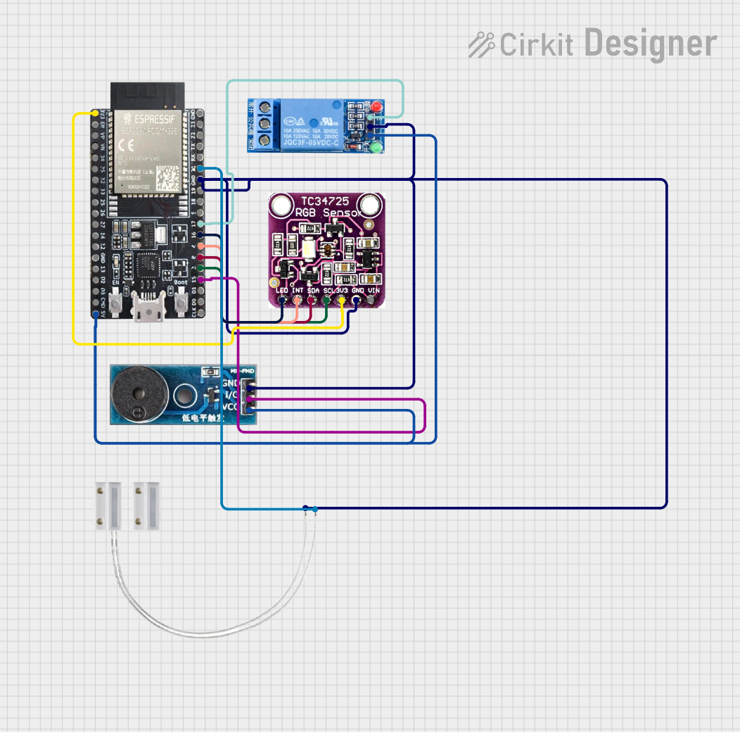
This circuit is designed to control a buzzer and a relay based on input from a TCS3472 color sensor and a Door MC-38 sensor using an ESP32 microcontroller. The buzzer and relay will be triggered every 5 minutes if there is a change in the color sensor. The system will stop if the door sensor is opened. If the door sensor is closed and the color sensor does not detect a change, the system will continue to trigger the buzzer and relay until the door sensor is opened and closed and the color sensor detects a change.
Component List
ESP32-WROOM
- Description: A powerful microcontroller with built-in Wi-Fi and Bluetooth capabilities.
- Pins: 3V3, EN, SP, SN, 34, 35, 32, 33, 25, 26, 27, 14, 12, GND, 13, 23, 22, TX0, RX0, 21, 19, 18, 5, 17, 16, 4, 0, 2, 15, SD1, SD0, CLK, 5V, CMD, SD3, SD2, USB
1 Channel Relay 5V
- Description: A relay module that allows the ESP32 to control high voltage devices.
- Pins: VCC, GND, IN, NC, COM, NO
TCS3472 COLOR LIGHT-TO-DIGITAL CONVERTER with IR FILTER
- Description: A color sensor that converts light to digital values.
- Pins: LED, INT, SDA, SCL, 3V3, GND, VIN
Door MC-38
- Description: A magnetic door sensor used to detect the state of a door (open or closed).
- Pins: S, GND
Buzzer Module
- Description: A module that produces sound when activated.
- Pins: GND, Vcc, I/O
Wiring Details
ESP32-WROOM
- 3V3: Connected to 3V3 of TCS3472 COLOR LIGHT-TO-DIGITAL CONVERTER with IR FILTER
- GND: Connected to GND of TCS3472 COLOR LIGHT-TO-DIGITAL CONVERTER with IR FILTER, 1 Channel Relay 5V, Buzzer Module, and Door MC-38
- 21: Connected to S of Door MC-38
- 17: Connected to IN of 1 Channel Relay 5V
- 16: Connected to LED of TCS3472 COLOR LIGHT-TO-DIGITAL CONVERTER with IR FILTER
- 4: Connected to INT of TCS3472 COLOR LIGHT-TO-DIGITAL CONVERTER with IR FILTER
- 0: Connected to SDA of TCS3472 COLOR LIGHT-TO-DIGITAL CONVERTER with IR FILTER
- 2: Connected to SCL of TCS3472 COLOR LIGHT-TO-DIGITAL CONVERTER with IR FILTER
- 15: Connected to I/O of Buzzer Module
- 5V: Connected to VCC of 1 Channel Relay 5V and Vcc of Buzzer Module
1 Channel Relay 5V
- VCC: Connected to 5V of ESP32-WROOM
- GND: Connected to GND of ESP32-WROOM
- IN: Connected to 17 of ESP32-WROOM
TCS3472 COLOR LIGHT-TO-DIGITAL CONVERTER with IR FILTER
- 3V3: Connected to 3V3 of ESP32-WROOM
- GND: Connected to GND of ESP32-WROOM
- LED: Connected to 16 of ESP32-WROOM
- INT: Connected to 4 of ESP32-WROOM
- SDA: Connected to 0 of ESP32-WROOM
- SCL: Connected to 2 of ESP32-WROOM
Door MC-38
- S: Connected to 21 of ESP32-WROOM
- GND: Connected to GND of ESP32-WROOM
Buzzer Module
- GND: Connected to GND of ESP32-WROOM
- Vcc: Connected to 5V of ESP32-WROOM
- I/O: Connected to 15 of ESP32-WROOM
Code Documentation
/*
 * This Arduino Sketch is designed for an ESP32 microcontroller to control a buzzer
 * and a relay based on input from a TCS3472 color sensor and a Door MC-38 sensor.
 * The buzzer and relay will be triggered every 5 minutes if there is a change in
 * the color sensor. The system will stop if the door sensor is opened. If the
 * door sensor is closed and the color sensor does not detect a change, the
 * system will continue to trigger the buzzer and relay until the door sensor is
 * opened and closed and the color sensor detects a change.
 */

#include <Wire.h>
#include "Adafruit_TCS34725.h"
#include "BluetoothSerial.h"

#define BUZZER_PIN 15
#define RELAY_PIN 17
#define DOOR_SENSOR_PIN 21
#define COLOR_SENSOR_LED_PIN 16

Adafruit_TCS34725 tcs = Adafruit_TCS34725(TCS34725_INTEGRATIONTIME_50MS, TCS34725_GAIN_4X);
BluetoothSerial SerialBT;

bool doorOpen = false;
uint16_t initialR, initialG, initialB, initialC;
const int debounceDelay = 50; // 50 milliseconds debounce delay
float colorChangeThreshold = 0.10; // 10% color change threshold
unsigned long colorCheckInterval = 300000; // 5 minutes in milliseconds

unsigned long lastDebounceTime = 0;
int lastDoorSensorState = HIGH;
int doorSensorState = HIGH;
unsigned long lastColorCheckTime = 0;

void setup() {
  pinMode(BUZZER_PIN, OUTPUT);
  pinMode(RELAY_PIN, OUTPUT);
  pinMode(DOOR_SENSOR_PIN, INPUT);
  pinMode(COLOR_SENSOR_LED_PIN, OUTPUT);
  digitalWrite(COLOR_SENSOR_LED_PIN, HIGH); // Turn on the color sensor LED

  Serial.begin(115200);
  SerialBT.begin("ESP32_BT"); // Bluetooth device name
  SerialBT.setPin("TAOM2024"); // Bluetooth password

  if (tcs.begin()) {
    Serial.println("Found color sensor");
    // Read initial color values
    tcs.getRawData(&initialR, &initialG, &initialB, &initialC);
  } else {
    Serial.println("No TCS34725 found ... check your connections");
    while (1); // Consider adding a more graceful error handling mechanism
  }
}

void loop() {
  int reading = digitalRead(DOOR_SENSOR_PIN);

  // Debounce the door sensor input
  if (reading != lastDoorSensorState) {
    lastDebounceTime = millis();
  }

  if ((millis() - lastDebounceTime) > debounceDelay) {
    if (reading != doorSensorState) {
      doorSensorState = reading;
      doorOpen = (doorSensorState == LOW);
    }
  }

  lastDoorSensorState = reading;

  if (doorOpen) {
    digitalWrite(BUZZER_PIN, LOW);
    digitalWrite(RELAY_PIN, LOW);
    return;
  }

  if (millis() - lastColorCheckTime >= colorCheckInterval) {
    lastColorCheckTime = millis();
    uint16_t r, g, b, c;
    tcs.getRawData(&r, &g, &b, &c);
    bool colorChanged = (abs(r - initialR) > initialR * colorChangeThreshold ||
                         abs(g - initialG) > initialG * colorChangeThreshold ||
                         abs(b - initialB) > initialB * colorChangeThreshold);

    if (colorChanged) {
      triggerBuzzerAndRelay();
    }
  }

  if (SerialBT.available()) {
    String command = SerialBT.readStringUntil('\n');
    processCommand(command);
  }
}

void triggerBuzzerAndRelay() {
  digitalWrite(BUZZER_PIN, HIGH);
  digitalWrite(RELAY_PIN, HIGH);
  delay(500);
  digitalWrite(BUZZER_PIN, LOW);
  digitalWrite(RELAY_PIN, LOW);
}

void processCommand(String command) {
  command.trim();
  if (command.startsWith("SET_THRESHOLD ")) {
    float newThreshold = command.substring(14).toFloat();
    if (newThreshold > 0 && newThreshold <= 1) {
      colorChangeThreshold = newThreshold;
      SerialBT.println("Threshold set to " + String(newThreshold * 100) + "%");
    } else {
      SerialBT.println("Invalid threshold value. Please enter a value between 0 and 1.");
    }
  } else if (command.startsWith("SET_INTERVAL ")) {
    unsigned long newInterval = command.substring(13).toInt() * 60000;
    if (newInterval > 0) {
      colorCheckInterval = newInterval;