Cirkit Designer
Your all-in-one circuit design IDE
Home /
Project Documentation
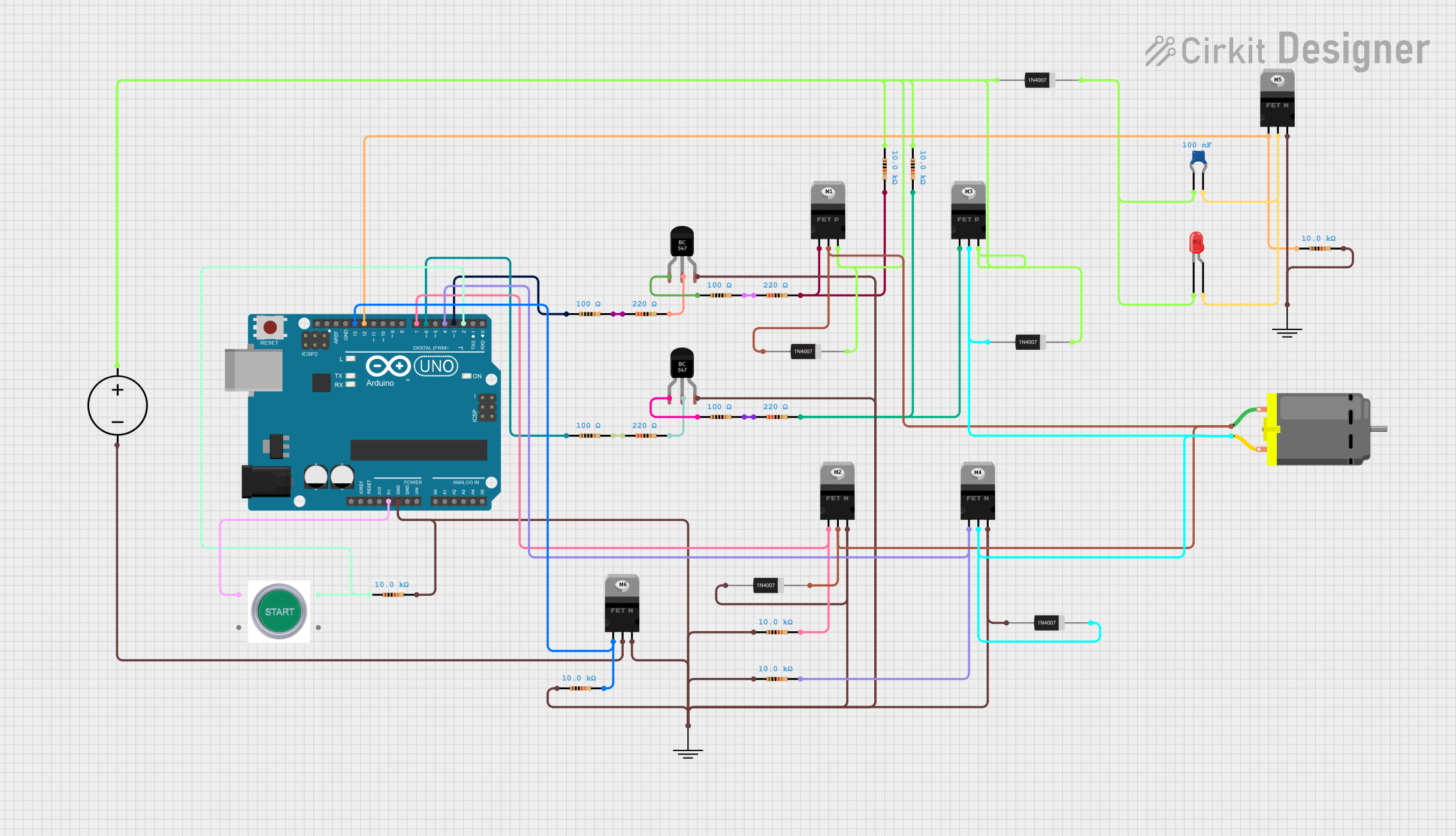
Arduino UNO Controlled DC Motor with Start Switch and Status LED
Circuit Documentation
Summary
This document provides a detailed overview of an electrical circuit that includes various components such as an Arduino UNO microcontroller, MOSFETs, transistors, resistors, diodes, a DC motor, a start switch, a DC power source, and a capacitor. The circuit appears to be designed for controlling a DC motor with input from a start switch and possibly other sensors or inputs, as indicated by the use of the Arduino UNO. The circuit includes power regulation and switching elements, as well as protection components like diodes.
Component List
Microcontroller
- Arduino UNO: A microcontroller board based on the ATmega328P. It has digital input/output pins, analog inputs, and various power outputs.
Transistors
- nMOS Transistor (MOSFET): A type of MOSFET used for switching and amplifying electronic signals.
- pMOS Transistor (MOSFET): A type of MOSFET that works inversely to nMOS, used for switching and amplifying electronic signals.
- BC547 Transistor: A general-purpose NPN bipolar junction transistor commonly used for low-power amplification and switching.
Passive Components
- Resistor: A passive two-terminal electrical component that implements electrical resistance as a circuit element.
- Ceramic Capacitor: A fixed-value capacitor where the ceramic material acts as the dielectric.
- 1N4007 Rectifier Diode: A standard silicon diode used to protect circuits by limiting the potential of reverse voltage spikes.
Electromechanical Components
- DC Motor: An electric motor that runs on direct current electricity.
- START SWITCH: A switch that likely serves as a user interface for starting the motor.
Power Supply
- DC Power Source: Provides the electrical energy required to power the circuit.
Indicators
- LED: Two Pin (red): A light-emitting diode that emits red light when powered.
Wiring Details
Arduino UNO
- 5V connected to START SWITCH (NO 1)
- GND connected to various GND pins of other components
- Digital pins (D2, D3, D4, D6, D7, D12, D13) connected to various resistors and MOSFET gates
nMOS Transistor (MOSFET)
- Gate connected to Arduino UNO or resistors
- Drain connected to DC Motor, diodes, or other MOSFETs
- Source connected to GND or other components
pMOS Transistor (MOSFET)
- Gate connected to resistors
- Drain connected to DC Motor and diodes
- Source connected to DC Power Source and resistors
BC547 Transistor
- Collector connected to resistors
- Base connected to resistors
- Emitter connected to GND
Resistor
- Connected between various components such as Arduino UNO pins, transistors, and GND
1N4007 Rectifier Diode
- Cathode connected to DC Motor, other diodes, or GND
- Anode connected to DC Motor, MOSFETs, or capacitor
DC Motor
- Pin 1 connected to pMOS Transistor, nMOS Transistor, and diode
- Pin 2 connected to pMOS Transistor, nMOS Transistor, and diode
START SWITCH
- NO 1 connected to Arduino UNO (5V)
- NO 2 connected to resistor and Arduino UNO (D2)
DC Power Source
- Ground connected to nMOS Transistor and GND
- Positive connected to pMOS Transistor, capacitor, and resistor
Ceramic Capacitor
- One pin connected to diode and LED
- Other pin connected to nMOS Transistor and LED
LED: Two Pin (red)
- Cathode connected to capacitor and diode
- Anode connected to capacitor
Documented Code
Arduino UNO Code (sketch.ino)
void setup() {
  // put your setup code here, to run once:

}

void loop() {
  // put your main code here, to run repeatedly:

}
Additional Notes
- The code provided for the Arduino UNO is a template with empty
setup()andloop()functions. Actual implementation details need to be filled in based on the specific requirements of the circuit's operation. - There is an additional text file (documentation.txt) mentioned, but it contains no code or information.