Arduino Nano-Based Heart Rate Monitoring System
Circuit Documentation
Summary
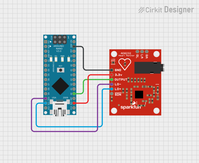
This document provides a detailed overview of a heart rate monitoring circuit that utilizes an Arduino Nano microcontroller in conjunction with an AD8232 Heart Rate Monitor module. The circuit is designed to capture heart rate signals and process them through the Arduino Nano for further analysis or display.
Component List
Arduino Nano
- Description: A compact microcontroller board based on the ATmega328P, featuring digital and analog I/O pins.
- Purpose: Acts as the central processing unit for the heart rate monitoring circuit, reading and processing signals from the AD8232 module.
AD8232 Heart Rate Monitor
- Description: A single-lead heart rate monitor analog front-end for wearable applications.
- Purpose: Captures electrical signals generated by the heart and outputs an analog signal representing the heart's activity.
Wiring Details
Arduino Nano
- Digital I/O Pins:
D10: Connected to the LO- (Lead-Off Detection Negative) of the AD8232 Heart Rate Monitor.D11/MOSI: Connected to the LO+ (Lead-Off Detection Positive) of the AD8232 Heart Rate Monitor.
- Analog Input Pins:
A0: Connected to the OUTPUT of the AD8232 Heart Rate Monitor to read the heart rate signal.
- Power Pins:
GND: Common ground with the AD8232 Heart Rate Monitor.3V3: Supplies 3.3V power to the AD8232 Heart Rate Monitor.
AD8232 Heart Rate Monitor
- Pins:
LO-: Connected toD10on the Arduino Nano for lead-off detection negative.LO+: Connected toD11/MOSIon the Arduino Nano for lead-off detection positive.GND: Common ground with the Arduino Nano.OUTPUT: The analog heart rate signal output connected toA0on the Arduino Nano.3.3v: Receives 3.3V power from the3V3pin on the Arduino Nano.
Documented Code
void setup() {
  // put your setup code here, to run once:

}

void loop() {
  // put your main code here, to run repeatedly:

}
File: sketch.ino
The provided code is a template for the Arduino Nano microcontroller. The setup() function is called once when the microcontroller is powered on or reset. It is used to initialize the settings, such as pin modes or serial communication parameters. The loop() function is called repeatedly and contains the main logic of the program. It is here where the Arduino would typically read the heart rate signal from the AD8232, process the data, and perform actions such as displaying the heart rate or sending the data to a computer for further analysis.
Note: The actual implementation code for reading and processing the heart rate signal is not provided in this document and should be developed according to the specific requirements of the application.