
Arduino and ESP8266 Nodemcu Based Health Monitoring System with MAX30102 and I2C LCD Display
View and Edit Project In Cirkit Designer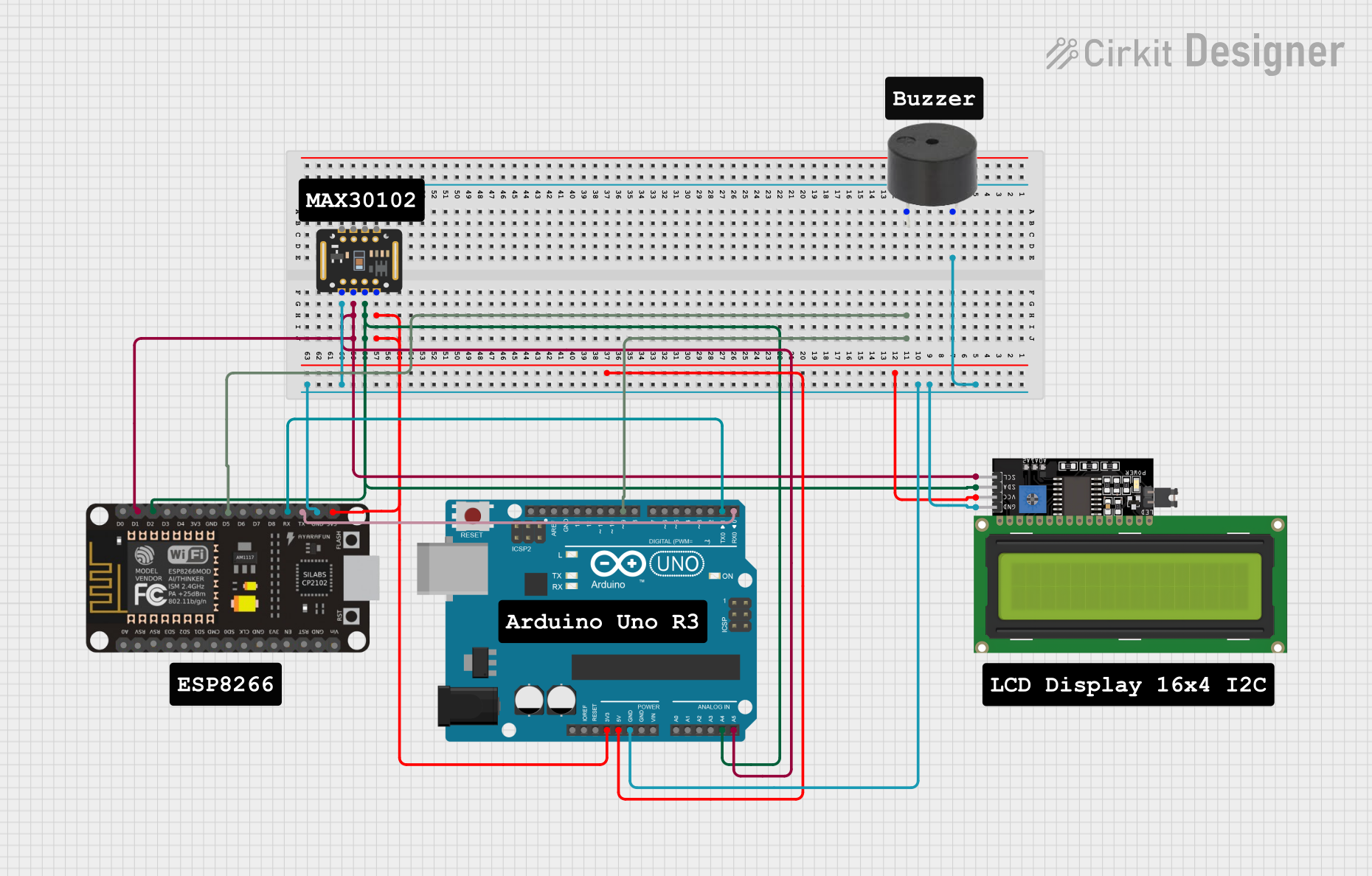
Circuit Documentation
Summary
This circuit integrates a variety of components including an Arduino UNO, an ESP8266 NodeMCU, a MAX30102 pulse oximeter sensor, an I2C LCD Display, and a buzzer. The Arduino UNO and ESP8266 NodeMCU are microcontrollers that serve as the brains of the circuit, allowing for programmable control and communication capabilities. The MAX30102 sensor is used for monitoring heart rate and blood oxygen levels, while the LCD display provides a user interface for displaying data. The buzzer can be used for audible alerts or feedback. The circuit is designed to be powered by the Arduino UNO's voltage supply pins, and it features I2C communication between the microcontrollers, sensor, and display.
Component List
Arduino UNO
- Microcontroller board based on the ATmega328P
- Features digital I/O pins, analog input pins, and various power output pins
MAX30102
- Pulse oximetry and heart-rate sensor
- Communicates over I2C interface
ESP8266 NodeMCU
- Wi-Fi enabled microcontroller module based on the ESP8266
- Features digital I/O pins and a single analog input pin
LCD Display 16x4 I2C
- Alphanumeric liquid crystal display with 16 characters by 4 lines
- Utilizes I2C communication for displaying data
Buzzer
- Simple piezoelectric buzzer for generating sound
Wiring Details
Arduino UNO
- GND connected to common ground
- 5V supplies power to the LCD Display
- 3.3V supplies power to the MAX30102 sensor
- A4 (SDA) connected to the I2C data line
- A5 (SCL) connected to the I2C clock line
- D9 connected to ESP8266 NodeMCU D5
- D0 (RX) connected to ESP8266 NodeMCU TX
- D1 (TX) connected to ESP8266 NodeMCU RX
MAX30102
- VIN connected to Arduino UNO 3.3V
- GND connected to common ground
- SDA connected to the I2C data line
- SCL connected to the I2C clock line
ESP8266 NodeMCU
- GND connected to common ground
- 3V3 connected to Arduino UNO 3.3V
- D1 (SCL) connected to the I2C clock line
- D2 (SDA) connected to the I2C data line
- D5 connected to Arduino UNO D9
- RX connected to Arduino UNO D1 (TX)
- TX connected to Arduino UNO D0 (RX)
LCD Display 16x4 I2C
- VCC connected to Arduino UNO 5V
- GND connected to common ground
- SDA connected to the I2C data line
- SCL connected to the I2C clock line
Buzzer
- PIN (not specified in the net list, assumed to be connected to a digital pin on a microcontroller for control)
- GND connected to common ground
Documented Code
Arduino UNO Code (sketch.ino)
void setup() {
  // put your setup code here, to run once:

}

void loop() {
  // put your main code here, to run repeatedly:

}
ESP8266 NodeMCU Code
No code provided for the ESP8266 NodeMCU in the input data.
Note: The provided code for the Arduino UNO is a template with no specific functionality. Additional code is required to interact with the connected components. The ESP8266 NodeMCU code is not included in the provided data and would need to be developed to fulfill the desired functions of the circuit.