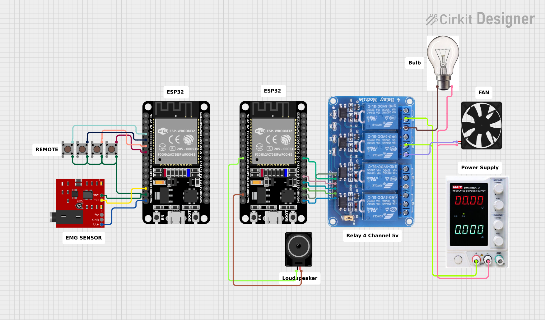
ESP32-Controlled Smart Relay with Muscle Sensor Activation

Circuit Documentation
Summary
The circuit in question appears to be a control system utilizing two ESP32 microcontrollers, interfaced with a variety of components including pushbuttons, an Advancer Muscle Sensor V3, a relay module, a loudspeaker, a bulb, a fan, and a power supply. The ESP32s are responsible for processing inputs from the pushbuttons and the muscle sensor, and controlling outputs like the loudspeaker, relay module, bulb, and fan. The relay module acts as an intermediary to control the high-power devices (bulb and fan) safely. The power supply provides the necessary voltage and current to the components.
Component List
Microcontrollers
- ESP32 (30 pin): A microcontroller with Wi-Fi and Bluetooth capabilities, featuring a wide range of GPIO pins for interfacing with various sensors and actuators.
Sensors
- Advancer Muscle Sensor V3: A sensor that measures muscle activity by detecting the electric potential generated by muscle cells.
Actuators
- Relay 4 Channel 5v: A module with four relays that can control high power devices such as motors and lights.
- Bulb: An electric light source.
- Fan: An electric device that creates airflow.
- Loudspeaker: An electroacoustic transducer that converts an electrical audio signal into a corresponding sound.
Input Devices
- Pushbutton: A simple switch mechanism for controlling some aspect of a machine or a process.
Power Supply
- Power Supply: Provides electrical power to the circuit.
Miscellaneous
- Comment: Used for annotations or notes within the circuit, not an actual physical component.
Wiring Details
ESP32 (30 pin)
- Digital Pins:
D34,D35,D32,D33are connected to pushbuttons.D13is connected to the signal output of the Advancer Muscle Sensor V3.D25is connected to the loudspeaker.D5,D4,D2,D15are connected to the relay module inputs.
- Power Pins:
Vinis connected to the positive voltage supply of the Advancer Muscle Sensor V3.3V3is connected to the VCC of the relay module.GNDis a common ground shared with pushbuttons, the muscle sensor, the loudspeaker, and the relay module.
Advancer Muscle Sensor V3
- Power Pins:
+Vsis connected toVinof the ESP32.GNDis connected to the common ground.
- Output Pin:
SIGis connected toD13of the ESP32.
Pushbutton
- One side of each pushbutton is connected to a digital pin on the ESP32 (
D34,D35,D32,D33). - The other side of each pushbutton is connected to the common ground.
Relay 4 Channel 5v
- Input Pins:
IN1,IN2,IN3,IN4are connected toD5,D4,D2,D15of the ESP32 respectively.
- Common Pins:
COM1,COM2are connected to the positive terminal of the power supply.
- Normally Open (NO) Pins:
NO1is connected to the bulb.NO2is connected to the fan.
- Power Pins:
VCCis connected to3V3of the ESP32.GNDis connected to the common ground.
Bulb
+VEis connected toNO1of the relay module._VEis connected to the negative terminal of the power supply.
Fan
5Vis connected toNO2of the relay module.GNDis connected to the negative terminal of the power supply.
Loudspeaker
pin1is connected toD25of the ESP32.pin2is connected to the common ground.
Power Supply
+is connected toCOM1andCOM2of the relay module.-is connected to the negative terminals of the bulb and the fan.
Documented Code
No code was provided for the microcontrollers in the circuit. For a complete documentation, the code should be included to illustrate how the ESP32 microcontrollers are programmed to interact with the sensors, actuators, and input devices.