
Arduino UNO-Based Smart Room Occupancy Detector with LDR and I2C LCD Display
View and Edit Project In Cirkit Designer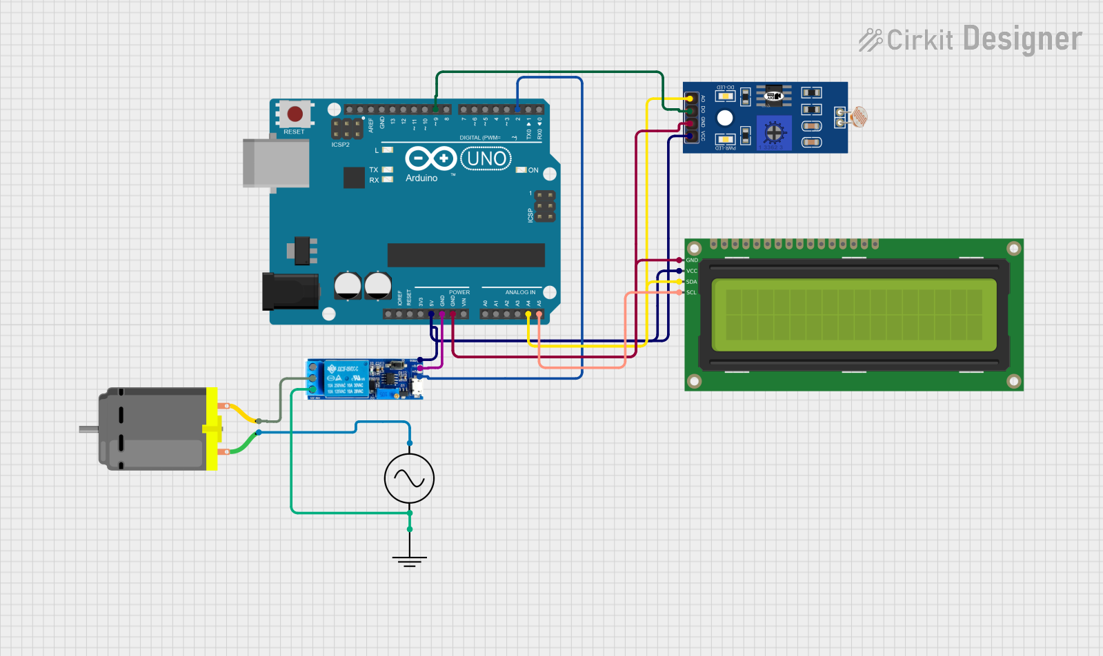
Circuit Documentation
Summary
This circuit is designed to control a DC motor using a relay module, an Arduino UNO, and an LDR (Light Dependent Resistor). The circuit also includes a 16x2 I2C LCD to display the status of the room (vacant or occupied) based on the LDR readings. The Arduino UNO serves as the central controller, reading the LDR status and controlling the relay module accordingly.
Component List
Relay Module 5V-30V
- Description: A relay module used to control high voltage devices with a low voltage signal.
- Pins: common contact, normally open, normally closed, trigger, V-, V+
Arduino UNO
- Description: A microcontroller board based on the ATmega328P, used for various embedded applications.
- Pins: UNUSED, IOREF, Reset, 3.3V, 5V, GND, Vin, A0, A1, A2, A3, A4, A5, SCL, SDA, AREF, D13, D12, D11, D10, D9, D8, D7, D6, D5, D4, D3, D2, D1, D0
LDR (Light Dependent Resistor)
- Description: A resistor whose resistance decreases with increasing incident light intensity.
- Pins: A0, D0, GND, VCC
16x2 I2C LCD
- Description: A 16x2 character LCD display with I2C interface.
- Pins: GND, VCC, SDA, SCL
AC Supply
- Description: An AC power supply.
- Pins: +ve, -ve
DC Motor
- Description: A motor that runs on direct current (DC).
- Pins: pin 1, pin 2
GND
- Description: Ground connection.
- Pins: GND
Wiring Details
Relay Module 5V-30V
- common contact connected to DC Motor pin 2
- normally closed connected to AC Supply -ve and GND GND
- trigger connected to 16x2 I2C LCD VCC, LDR VCC, and Arduino UNO 5V
- V- connected to Arduino UNO GND
- V+ connected to Arduino UNO D2
Arduino UNO
- 5V connected to Relay Module trigger, 16x2 I2C LCD VCC, and LDR VCC
- GND connected to Relay Module V-, 16x2 I2C LCD GND, and LDR GND
- A4 connected to 16x2 I2C LCD SDA and LDR A0
- A5 connected to 16x2 I2C LCD SCL
- D2 connected to Relay Module V+
- D9 connected to LDR D0
LDR
- VCC connected to Arduino UNO 5V
- GND connected to Arduino UNO GND
- A0 connected to Arduino UNO A4 and 16x2 I2C LCD SDA
- D0 connected to Arduino UNO D9
16x2 I2C LCD
- VCC connected to Arduino UNO 5V
- GND connected to Arduino UNO GND
- SDA connected to Arduino UNO A4 and LDR A0
- SCL connected to Arduino UNO A5
AC Supply
- +ve connected to DC Motor pin 1
- -ve connected to Relay Module normally closed and GND GND
DC Motor
- pin 1 connected to AC Supply +ve
- pin 2 connected to Relay Module common contact
GND
- GND connected to AC Supply -ve and Relay Module normally closed
Code Documentation
#include <LiquidCrystal_I2C.h>

LiquidCrystal_I2C lcd(0x27, 16, 2);

int ldr = 9;
int relay = 2;
int dtime = 100;

void setup() {
  pinMode(relay, OUTPUT);
  lcd.init();
  lcd.backlight();
}

void loop() {
  int ldrStatus = digitalRead(ldr);

  if (ldrStatus) {
    digitalWrite(relay, HIGH);
    lcd.clear();
    lcd.println("ROOM VACANT");
    lcd.setCursor(1, 0);
    delay(dtime);
  } else {
    digitalWrite(relay, LOW);
    lcd.clear();
    lcd.println("ROOM OCCUPIED");
    lcd.setCursor(1, 1);
    delay(dtime);
  }
}
Code Explanation
- Libraries: The
LiquidCrystal_I2Clibrary is included to control the 16x2 I2C LCD. - Variables:
lcd: Initializes the LCD with I2C address0x27, 16 columns, and 2 rows.ldr: Pin number for the LDR (connected to D9).relay: Pin number for the relay module (connected to D2).dtime: Delay time in milliseconds.
- Setup Function:
pinMode(relay, OUTPUT): Sets the relay pin as an output.lcd.init(): Initializes the LCD.lcd.backlight(): Turns on the LCD backlight.
- Loop Function:
ldrStatus: Reads the status of the LDR.- If the LDR status is high (room is vacant), the relay is turned on, and the LCD displays "ROOM VACANT".
- If the LDR status is low (room is occupied), the relay is turned off, and the LCD displays "ROOM OCCUPIED".
- The
delay(dtime)function is used to create a delay between status checks.