Cirkit Designer
Your all-in-one circuit design IDE
Home /
Project Documentation
ESP32-Controlled I2C LCD Display and Relay Module
Circuit Documentation
Summary of the Circuit
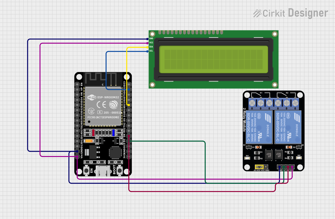
This circuit integrates an ESP32 microcontroller with an I2C LCD 16x2 screen and a 2-channel relay module. The ESP32 is programmed to display messages on the LCD screen and control the relay module. The LCD screen is interfaced with the ESP32 via the I2C protocol, and the relay module is controlled through GPIO pins. The circuit is designed to operate with a common ground and power supply for all components.
Component List
ESP32 (30 pin)
- Description: A microcontroller with Wi-Fi and Bluetooth capabilities, featuring a wide range of GPIO pins.
- Pins: EN, VP, VN, D34, D35, D32, D33, D25, D26, D27, D14, D12, D13, GND, Vin, D23, D22, TX0, RX0, D21, D19, D18, D5, TX2, RX2, D4, D2, D15, 3V3
I2C LCD 16x2 Screen
- Description: A 16x2 character LCD display that uses the I2C bus for communication.
- Pins: SCL, SDA, VCC (5V), GND, VDD, VO, RS, RW, E, D0, D1, D2, D3, D4, D5, D6, D7, BLA, BLK
Relay Module 2 Channel
- Description: A module with two relays that can be independently controlled, typically used for switching high power devices.
- Pins: GND, IN1, IN2, VCC, NC1, COM, NO1, NC2, NO2
Wiring Details
ESP32 (30 pin)
- GND connected to the GND of the I2C LCD screen and the GND of the Relay Module.
- Vin connected to the VCC (5V) of the I2C LCD screen and the VCC of the Relay Module.
- D22 (SCL) connected to the SCL pin of the I2C LCD screen.
- D21 (SDA) connected to the SDA pin of the I2C LCD screen.
- D4 connected to the IN2 pin of the Relay Module.
- D2 connected to the IN1 pin of the Relay Module.
I2C LCD 16x2 Screen
- SCL connected to the D22 pin of the ESP32.
- SDA connected to the D21 pin of the ESP32.
- VCC (5V) connected to the Vin of the ESP32.
- GND connected to the GND of the ESP32.
Relay Module 2 Channel
- GND connected to the GND of the ESP32.
- IN1 connected to the D2 pin of the ESP32.
- IN2 connected to the D4 pin of the ESP32.
- VCC connected to the Vin of the ESP32.
Documented Code
/*
 * This Arduino Sketch interfaces an ESP32 with an I2C LCD 16x2 screen.
 * The ESP32 displays two messages on the LCD screen in a loop with delays.
 * Connections:
 * - ESP32 GND to LCD GND
 * - ESP32 Vin to LCD VCC (5V)
 * - ESP32 D22 to LCD SCL
 * - ESP32 D21 to LCD SDA
 */

#include <Wire.h>
#include <LiquidCrystal_I2C.h>

LiquidCrystal_I2C lcd(0x27, 16, 2);

void setup() {
  Serial.begin(115200);
  lcd.init();
  lcd.backlight();
  lcd.print("Welcome");
  delay(2000);
  lcd.init();
  lcd.backlight();
  lcd.print("EV 22CHRG");
  delay(2000);
}

void loop() {
  delay(1000);
  lcd.clear();
  lcd.setCursor(0, 0);
  lcd.print("SLOT1");
  delay(2000);
}
Filename: sketch.ino
Description: The code initializes the I2C LCD screen and prints a welcome message followed by "EV 22CHRG". In the loop, it periodically clears the screen and prints "SLOT1". The ESP32 communicates with the LCD via I2C, using pins D22 for SCL and D21 for SDA. The relay module is not controlled in this code snippet.