
Arduino UNO Dual Stepper Motor Control with Light-Dependent Resistors
View and Edit Project In Cirkit Designer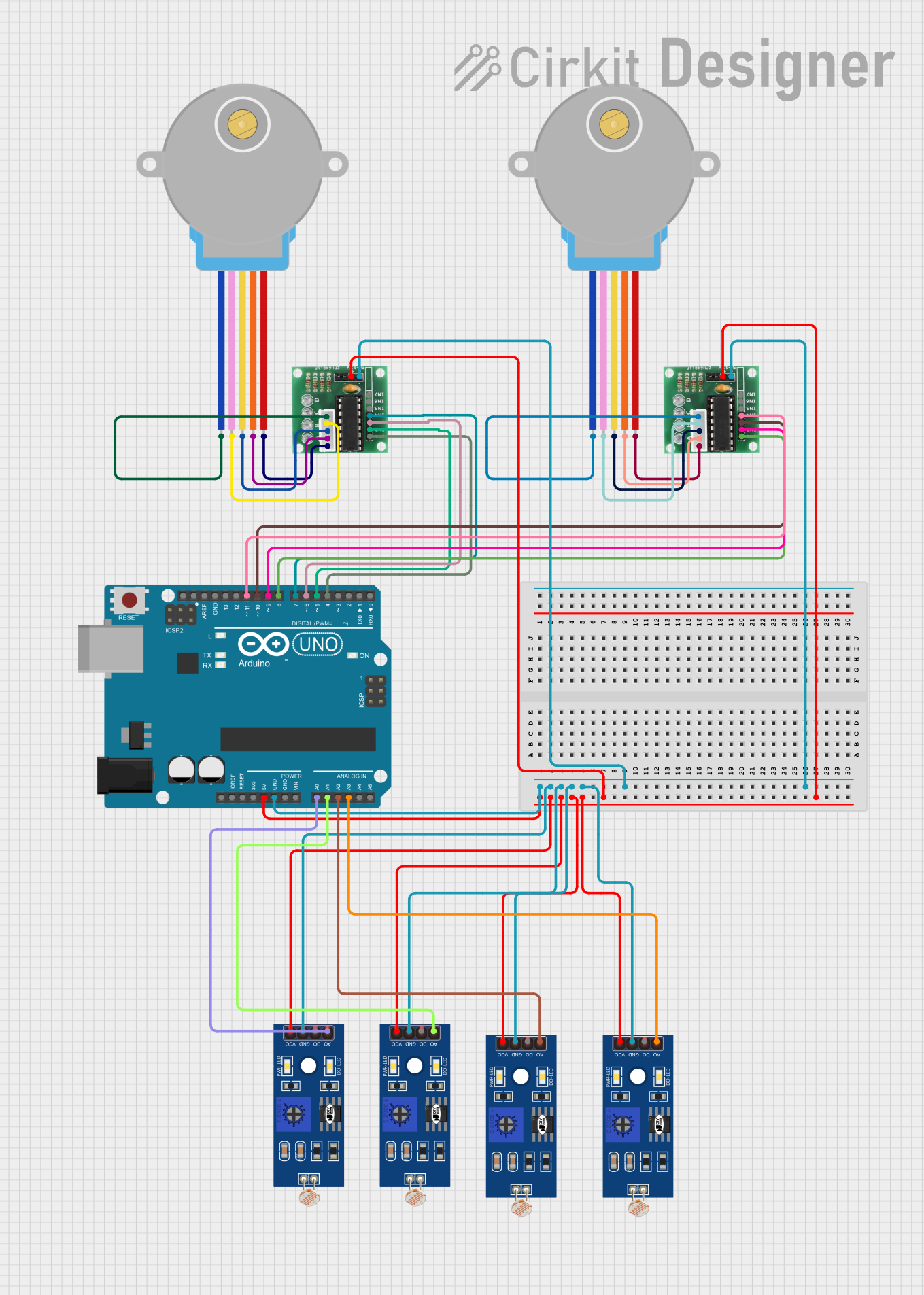
Circuit Documentation
Summary
This circuit involves an Arduino UNO microcontroller controlling two 28BYJ-48 stepper motors through two ULN 2003 driver ICs. Additionally, the circuit includes four Light Dependent Resistors (LDRs) for light sensing. The Arduino UNO is programmed to control the stepper motors and read data from the LDRs.
Component List
28BYJ-48 Stepper Motor
- Description: A small, inexpensive stepper motor commonly used in various applications.
- Pins: BLUE, PINK, YELLOW, ORANGE, RED
ULN 2003
- Description: A high-voltage, high-current Darlington transistor array used to drive the stepper motors.
- Pins: IN1, IN2, IN3, IN4, IN5, IN6, IN7, GND, +, COIL1, COIL2, COIL3, COIL4, COIL5
Arduino UNO
- Description: A microcontroller board based on the ATmega328P, used to control the stepper motors and read data from the LDRs.
- Pins: UNUSED, IOREF, Reset, 3.3V, 5V, GND, Vin, A0, A1, A2, A3, A4, A5, SCL, SDA, AREF, D13, D12, D11, D10, D9, D8, D7, D6, D5, D4, D3, D2, D1, D0
LDR (Light Dependent Resistor)
- Description: A resistor whose resistance decreases with increasing incident light intensity.
- Pins: A0, D0, GND, VCC
Wiring Details
28BYJ-48 Stepper Motor 1
- BLUE connected to COIL5 of ULN 2003
- PINK connected to COIL4 of ULN 2003
- YELLOW connected to COIL3 of ULN 2003
- ORANGE connected to COIL2 of ULN 2003
- RED connected to COIL1 of ULN 2003
28BYJ-48 Stepper Motor 2
- BLUE connected to COIL5 of ULN 2003
- PINK connected to COIL4 of ULN 2003
- YELLOW connected to COIL3 of ULN 2003
- ORANGE connected to COIL2 of ULN 2003
- RED connected to COIL1 of ULN 2003
ULN 2003 (Driver for Stepper Motor 1)
- IN1 connected to D4 of Arduino UNO
- IN2 connected to D5 of Arduino UNO
- IN3 connected to D6 of Arduino UNO
- IN4 connected to D7 of Arduino UNO
- GND connected to GND of Arduino UNO
- + connected to 5V of Arduino UNO
ULN 2003 (Driver for Stepper Motor 2)
- IN1 connected to D8 of Arduino UNO
- IN2 connected to D9 of Arduino UNO
- IN3 connected to D10 of Arduino UNO
- IN4 connected to D11 of Arduino UNO
- GND connected to GND of Arduino UNO
- + connected to 5V of Arduino UNO
Arduino UNO
- D4 connected to IN1 of ULN 2003 (Driver for Stepper Motor 1)
- D5 connected to IN2 of ULN 2003 (Driver for Stepper Motor 1)
- D6 connected to IN3 of ULN 2003 (Driver for Stepper Motor 1)
- D7 connected to IN4 of ULN 2003 (Driver for Stepper Motor 1)
- D8 connected to IN1 of ULN 2003 (Driver for Stepper Motor 2)
- D9 connected to IN2 of ULN 2003 (Driver for Stepper Motor 2)
- D10 connected to IN3 of ULN 2003 (Driver for Stepper Motor 2)
- D11 connected to IN4 of ULN 2003 (Driver for Stepper Motor 2)
- A0 connected to A0 of LDR
- A1 connected to A0 of LDR
- A2 connected to A0 of LDR
- A3 connected to A0 of LDR
- GND connected to GND of ULN 2003 (both drivers) and GND of all LDRs
- 5V connected to + of ULN 2003 (both drivers) and VCC of all LDRs
LDR (Light Dependent Resistor) 1
- A0 connected to A0 of Arduino UNO
- GND connected to GND of Arduino UNO
- VCC connected to 5V of Arduino UNO
LDR (Light Dependent Resistor) 2
- A0 connected to A1 of Arduino UNO
- GND connected to GND of Arduino UNO
- VCC connected to 5V of Arduino UNO
LDR (Light Dependent Resistor) 3
- A0 connected to A2 of Arduino UNO
- GND connected to GND of Arduino UNO
- VCC connected to 5V of Arduino UNO
LDR (Light Dependent Resistor) 4
- A0 connected to A3 of Arduino UNO
- GND connected to GND of Arduino UNO
- VCC connected to 5V of Arduino UNO
Documented Code
Arduino UNO Code (sketch.ino)
void setup() {
  // put your setup code here, to run once:

}

void loop() {
  // put your main code here, to run repeatedly:

}
Documentation (documentation.txt)
This documentation provides a comprehensive overview of the circuit, including a summary, detailed component list, wiring details, and the code used in the Arduino UNO microcontroller.