Cirkit Designer
Your all-in-one circuit design IDE
Home /
Project Documentation
Arduino UNO Controlled 8-Relay Module with Pushbutton Activation
Circuit Documentation
Summary
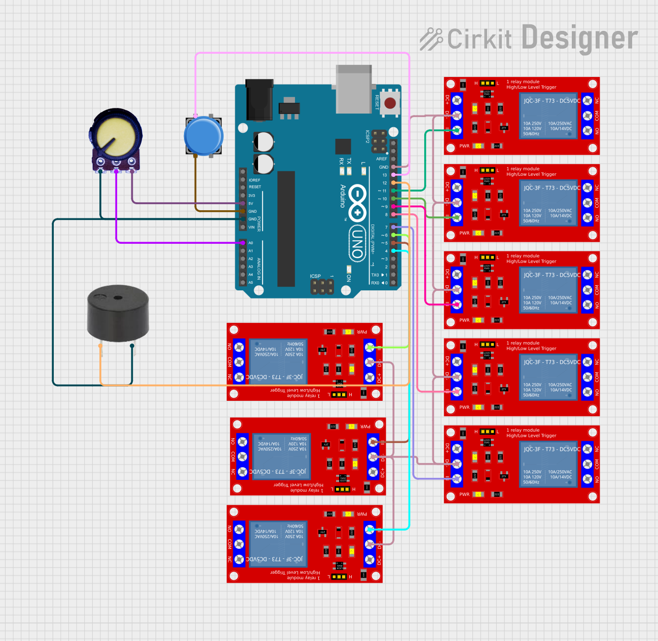
This circuit utilizes an Arduino UNO to control eight 1 Channel 5V Relay Modules, a pushbutton, a potentiometer, and a buzzer. The pushbutton is used to sequentially activate each relay for 150 seconds. The potentiometer is used to provide an analog input to the Arduino, and the buzzer is used for audio feedback.
Component List
Arduino UNO
- Description: A microcontroller board based on the ATmega328P.
- Pins: UNUSED, IOREF, Reset, 3.3V, 5V, GND, Vin, A0, A1, A2, A3, A4, A5, SCL, SDA, AREF, D13, D12, D11, D10, D9, D8, D7, D6, D5, D4, D3, D2, D1, D0
1 Channel 5V Relay Module
- Description: A relay module that allows control of high voltage devices with a low voltage signal.
- Pins: VCC+, VCC- (GND), IN, N.O., COM, N.C.
Pushbutton
- Description: A simple pushbutton switch.
- Pins: Pin 2, Pin 1, Pin 3, Pin 4
Potentiometer
- Description: A variable resistor used to provide an adjustable voltage.
- Pins: GND, Output, VCC
Buzzer
- Description: An audio signaling device.
- Pins: PIN, GND
Wiring Details
Arduino UNO
- 5V connected to VCC of Potentiometer
- GND connected to:
- Pin 2 of Pushbutton
- GND of Buzzer
- GND of Potentiometer
- VCC- (GND) of all 1 Channel 5V Relay Modules
- A0 connected to Output of Potentiometer
- D13 connected to Pin 1 of Pushbutton
- D12 connected to PIN of Buzzer
- D11 connected to IN of 1 Channel 5V Relay Module
- D10 connected to IN of 1 Channel 5V Relay Module
- D9 connected to IN of 1 Channel 5V Relay Module
- D8 connected to IN of 1 Channel 5V Relay Module
- D7 connected to IN of 1 Channel 5V Relay Module
- D6 connected to IN of 1 Channel 5V Relay Module
- D5 connected to IN of 1 Channel 5V Relay Module
- D4 connected to IN of 1 Channel 5V Relay Module
1 Channel 5V Relay Module
- VCC- (GND) connected to GND of Arduino UNO
- IN connected to:
- D11 of Arduino UNO
- D10 of Arduino UNO
- D9 of Arduino UNO
- D8 of Arduino UNO
- D7 of Arduino UNO
- D6 of Arduino UNO
- D5 of Arduino UNO
- D4 of Arduino UNO
Pushbutton
- Pin 2 connected to GND of Arduino UNO
- Pin 1 connected to D13 of Arduino UNO
Potentiometer
- VCC connected to 5V of Arduino UNO
- GND connected to GND of Arduino UNO
- Output connected to A0 of Arduino UNO
Buzzer
- PIN connected to D12 of Arduino UNO
- GND connected to GND of Arduino UNO
Code Documentation
/*
 * This Arduino sketch controls 8 relays using a pushbutton. When the button
 * is pressed, each relay is activated sequentially for 150 seconds.
 */

#define PUSHBUTTON_PIN 2

int relayPins[] = {11, 10, 9, 8, 7, 6, 5, 4};

void setup() {
  pinMode(PUSHBUTTON_PIN, INPUT_PULLUP);
  for (int i = 0; i < 8; i++) {
    pinMode(relayPins[i], OUTPUT);
    digitalWrite(relayPins[i], LOW);
  }
}

void loop() {
  if (digitalRead(PUSHBUTTON_PIN) == LOW) {
    for (int i = 0; i < 8; i++) {
      digitalWrite(relayPins[i], HIGH);
      delay(150000);
      digitalWrite(relayPins[i], LOW);
    }
  }
}
- PUSHBUTTON_PIN: Defines the pin connected to the pushbutton.
- relayPins[]: An array holding the pin numbers connected to the relay modules.
- setup(): Initializes the pushbutton pin as an input with an internal pull-up resistor and sets all relay pins as outputs, initially set to LOW.
- loop(): Continuously checks if the pushbutton is pressed. If pressed, it sequentially activates each relay for 150 seconds.