Cirkit Designer
Your all-in-one circuit design IDE
Home /
Project Documentation
Arduino-Based Rain Detection System with YL-83 Sensor
Circuit Documentation
Summary
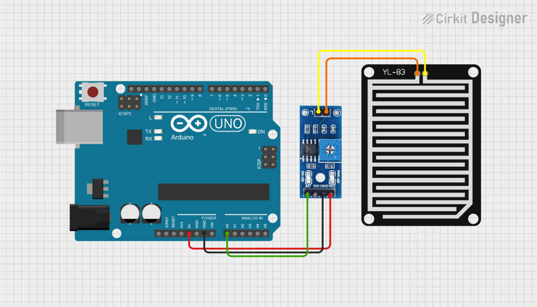
This circuit involves an Arduino UNO microcontroller interfacing with a Rain/Snow Sensor and a YL-83 Rain Sensor Detection Board. The purpose of this setup is to detect rain or snow and potentially trigger actions based on the sensor readings.
Component List
Arduino UNO
- Description: A microcontroller board based on the ATmega328P.
- Pins: UNUSED, IOREF, Reset, 3.3V, 5V, GND, Vin, A0, A1, A2, A3, A4, A5, SCL, SDA, AREF, D13, D12, D11, D10, D9, D8, D7, D6, D5, D4, D3, D2, D1, D0
Rain/Snow Sensor - Board
- Description: A sensor board used to detect rain or snow.
- Pins: 1, 2, A0 (Analog), D0 (Digital), GND, VCC (5V)
YL-83 Rain Sensor - Detection Board
- Description: A detection board used in conjunction with the Rain/Snow Sensor to detect the presence of rain.
- Pins: POS, NEG
Wiring Details
Arduino UNO
- 5V: Connected to VCC (5V) of the Rain/Snow Sensor - Board
- GND: Connected to GND of the Rain/Snow Sensor - Board
- A0: Connected to A0 (Analog) of the Rain/Snow Sensor - Board
Rain/Snow Sensor - Board
- VCC (5V): Connected to 5V of the Arduino UNO
- GND: Connected to GND of the Arduino UNO
- A0 (Analog): Connected to A0 of the Arduino UNO
- 1: Connected to NEG of the YL-83 Rain Sensor - Detection Board
- 2: Connected to POS of the YL-83 Rain Sensor - Detection Board
YL-83 Rain Sensor - Detection Board
- NEG: Connected to 1 of the Rain/Snow Sensor - Board
- POS: Connected to 2 of the Rain/Snow Sensor - Board
Code Documentation
Arduino UNO Code
sketch.ino
void setup() {
  // put your setup code here, to run once:

}

void loop() {
  // put your main code here, to run repeatedly:

}
documentation.txt
This documentation provides a comprehensive overview of the circuit, including the components used, their wiring details, and the code running on the Arduino UNO.