
Arduino Nano-Based Smart Motor Control System with IR Sensor and Vibration Feedback
View and Edit Project In Cirkit Designer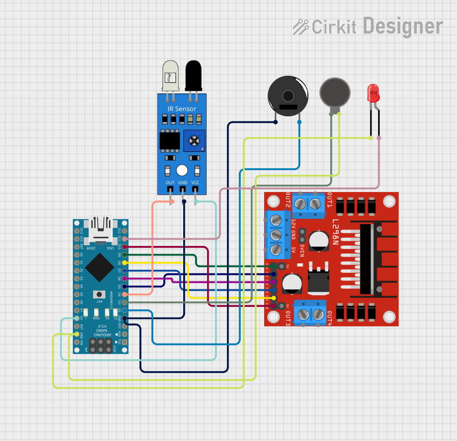
Circuit Documentation
Summary
This document provides a detailed overview of a circuit that includes an Arduino Nano microcontroller, an L298N DC motor driver, an IR sensor, a Piezo Buzzer, a Vibration Motor, and a red LED. The circuit is designed to interface these components with the Arduino Nano, allowing for control and interaction through the microcontroller.
Component List
Arduino Nano
- Description: A small, complete, and breadboard-friendly board based on the ATmega328P.
- Pins: D1/TX, D0/RX, RESET, GND, D2, D3, D4, D5, D6, D7, D8, D9, D10, D11/MOSI, D12/MISO, VIN, 5V, A7, A6, A5, A4, A3, A2, A1, A0, AREF, 3V3, D13/SCK
L298N DC Motor Driver
- Description: A dual H-Bridge motor driver that allows for control of two DC motors.
- Pins: OUT1, OUT2, 12V, GND, 5V, OUT3, OUT4, 5V-ENA-JMP-I, 5V-ENA-JMP-O, +5V-J1, +5V-J2, ENA, IN1, IN2, IN3, IN4, ENB
IR Sensor
- Description: An infrared sensor used for detecting objects or measuring distance.
- Pins: out, gnd, vcc
Piezo Buzzer
- Description: A small audio device that produces sound when a voltage is applied.
- Pins: pin 1, pin 2
Vibration Motor
- Description: A small motor that provides vibration feedback.
- Pins: +, -
LED: Two Pin (Red)
- Description: A standard red LED with two pins.
- Pins: cathode, anode
Wiring Details
Arduino Nano
- GND: Connected to Piezo Buzzer pin 1, IR Sensor gnd, Vibration Motor -, and LED cathode.
- D2: Connected to Piezo Buzzer pin 2.
- D3: Connected to Vibration Motor +.
- D4: Connected to IR Sensor out.
- D5: Connected to L298N DC Motor Driver IN1.
- D6: Connected to L298N DC Motor Driver IN2.
- D7: Connected to L298N DC Motor Driver IN3.
- D8: Connected to L298N DC Motor Driver IN4.
- D9: Connected to L298N DC Motor Driver ENA.
- D10: Connected to L298N DC Motor Driver ENB.
- D11/MOSI: Connected to LED anode.
- 5V: Connected to IR Sensor vcc.
L298N DC Motor Driver
- IN1: Connected to Arduino Nano D5.
- IN2: Connected to Arduino Nano D6.
- IN3: Connected to Arduino Nano D7.
- IN4: Connected to Arduino Nano D8.
- ENA: Connected to Arduino Nano D9.
- ENB: Connected to Arduino Nano D10.
IR Sensor
- gnd: Connected to Arduino Nano GND.
- out: Connected to Arduino Nano D4.
- vcc: Connected to Arduino Nano 5V.
Piezo Buzzer
- pin 1: Connected to Arduino Nano GND.
- pin 2: Connected to Arduino Nano D2.
Vibration Motor
- +: Connected to Arduino Nano D3.
- -: Connected to Arduino Nano GND.
LED: Two Pin (Red)
- cathode: Connected to Arduino Nano GND.
- anode: Connected to Arduino Nano D11/MOSI.
Documented Code
Arduino Nano Code
void setup() {
  // put your setup code here, to run once:

}

void loop() {
  // put your main code here, to run repeatedly:

}
This code is a basic template for the Arduino Nano. The setup() function is where you initialize your components, and the loop() function is where you place the main code that runs repeatedly.
Additional Documentation
// This file is intended for additional documentation purposes.
This section is reserved for any additional documentation or notes that may be required for understanding the circuit or the code.