Cirkit Designer
Your all-in-one circuit design IDE
Home /
Project Documentation
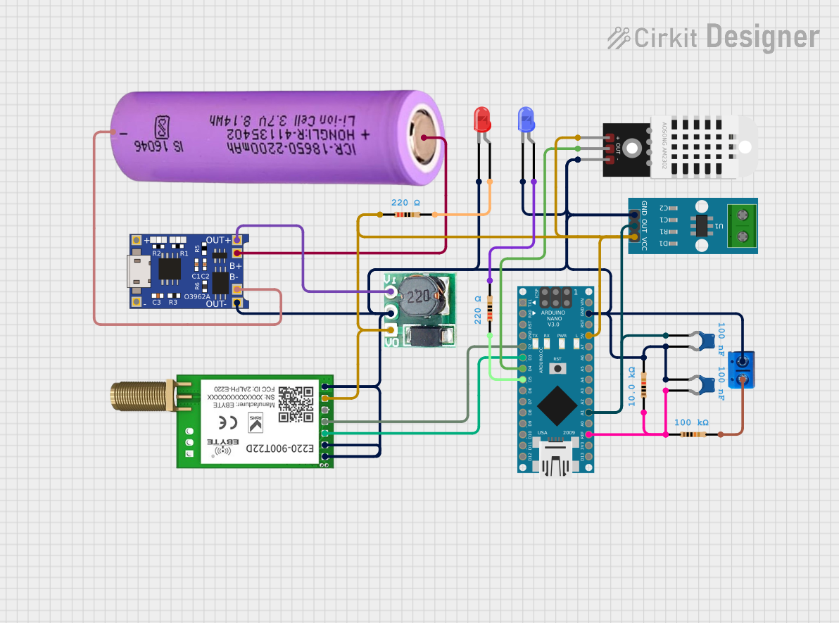
Battery-Powered Arduino Nano Weather Station with LoRa Communication
Circuit Documentation
Summary
This document provides a detailed overview of a circuit that includes various components such as sensors, microcontrollers, resistors, capacitors, LEDs, and communication modules. The circuit is designed to interface with an Arduino Nano, which controls and processes data from the connected components. The circuit also includes power management components to ensure stable operation.
Component List
DHT22
- Description: Digital temperature and humidity sensor
- Pins: +, Out, -
Battery 18650
- Description: Rechargeable lithium-ion battery
- Pins: +, -
Resistor (10k Ohms)
- Description: Resistor with a resistance of 10k Ohms
- Pins: pin1, pin2
Arduino Nano
- Description: Microcontroller board based on the ATmega328
- Pins: D1/TX, D0/RX, RESET, GND, D2, D3, D4, D5, D6, D7, D8, D9, D10, D11/MOSI, D12/MISO, VIN, 5V, A7, A6, A5, A4, A3, A2, A1, A0, AREF, 3V3, D13/SCK
Resistor (100k Ohms)
- Description: Resistor with a resistance of 100k Ohms
- Pins: pin1, pin2
Terminal PCB 2 Pin
- Description: 2-pin terminal block for PCB
- Pins: Pin A, Pin B
TP4056
- Description: Lithium battery charger module
- Pins: OUT-, B-, B+, OUT+, IN-, IN+
Step Up Boost 3v-5v
- Description: DC-DC step-up converter
- Pins: Vi, GND, Vo
Ceramic Capacitor (0.1uF)
- Description: Ceramic capacitor with a capacitance of 0.1uF
- Pins: pin0, pin1
Resistor (220 Ohms)
- Description: Resistor with a resistance of 220 Ohms
- Pins: pin1, pin2
LED: Two Pin (blue)
- Description: Blue LED
- Pins: cathode, anode
LED: Two Pin (red)
- Description: Red LED
- Pins: cathode, anode
EBYTE LoRa E220
- Description: LoRa communication module
- Pins: M0, M1, RXD, TXD, AUX, VCC, GND
ACS712 Current Sensor 5A 20A 30A
- Description: Current sensor module
- Pins: 1, 2, GND, OUT, VCC
Wiring Details
DHT22
- + connected to Step Up Boost 3v-5v Vo
- Out connected to Arduino Nano D4
- - connected to GND
Battery 18650
- + connected to TP4056 B+
- - connected to TP4056 B-
Resistor (10k Ohms)
- pin1 connected to Arduino Nano AREF
- pin2 connected to Terminal PCB 2 Pin Pin A
Arduino Nano
- D2 connected to EBYTE LoRa E220 TXD
- D3 connected to EBYTE LoRa E220 RXD
- D4 connected to DHT22 Out
- D5 connected to Resistor (220 Ohms) pin1
- GND connected to GND
- 5V connected to Step Up Boost 3v-5v Vo
- A1 connected to ACS712 Current Sensor 5A 20A 30A OUT
- AREF connected to Resistor (100k Ohms) pin1
Resistor (100k Ohms)
- pin1 connected to Arduino Nano AREF
- pin2 connected to Terminal PCB 2 Pin Pin A
Terminal PCB 2 Pin
- Pin A connected to Resistor (100k Ohms) pin2
- Pin B connected to GND
TP4056
- OUT- connected to GND
- B- connected to Battery 18650 -
- B+ connected to Battery 18650 +
- OUT+ connected to Step Up Boost 3v-5v Vi
Step Up Boost 3v-5v
- Vi connected to TP4056 OUT+
- GND connected to GND
- Vo connected to Arduino Nano 5V
Ceramic Capacitor (0.1uF)
- pin0 connected to GND
- pin1 connected to Step Up Boost 3v-5v GND
Resistor (220 Ohms)
- pin1 connected to Arduino Nano D5
- pin2 connected to LED: Two Pin (blue) anode
LED: Two Pin (blue)
- cathode connected to GND
- anode connected to Resistor (220 Ohms) pin2
LED: Two Pin (red)
- cathode connected to GND
- anode connected to Resistor (220 Ohms) pin2
EBYTE LoRa E220
- TXD connected to Arduino Nano D2
- RXD connected to Arduino Nano D3
- M0 connected to GND
- M1 connected to GND
- GND connected to GND
- VCC connected to Step Up Boost 3v-5v Vo
ACS712 Current Sensor 5A 20A 30A
- 1 not connected
- 2 not connected
- GND connected to GND
- OUT connected to Arduino Nano A1
- VCC connected to Step Up Boost 3v-5v Vo
Documented Code
Arduino Nano Code
void setup() {
  // put your setup code here, to run once:

}

void loop() {
  // put your main code here, to run repeatedly:

}
This concludes the documentation for the circuit. Each component is described along with its connections, and the code for the Arduino Nano is provided.