
Arduino UNO Controlled Smart Irrigation and Environmental Monitoring System
View and Edit Project In Cirkit Designer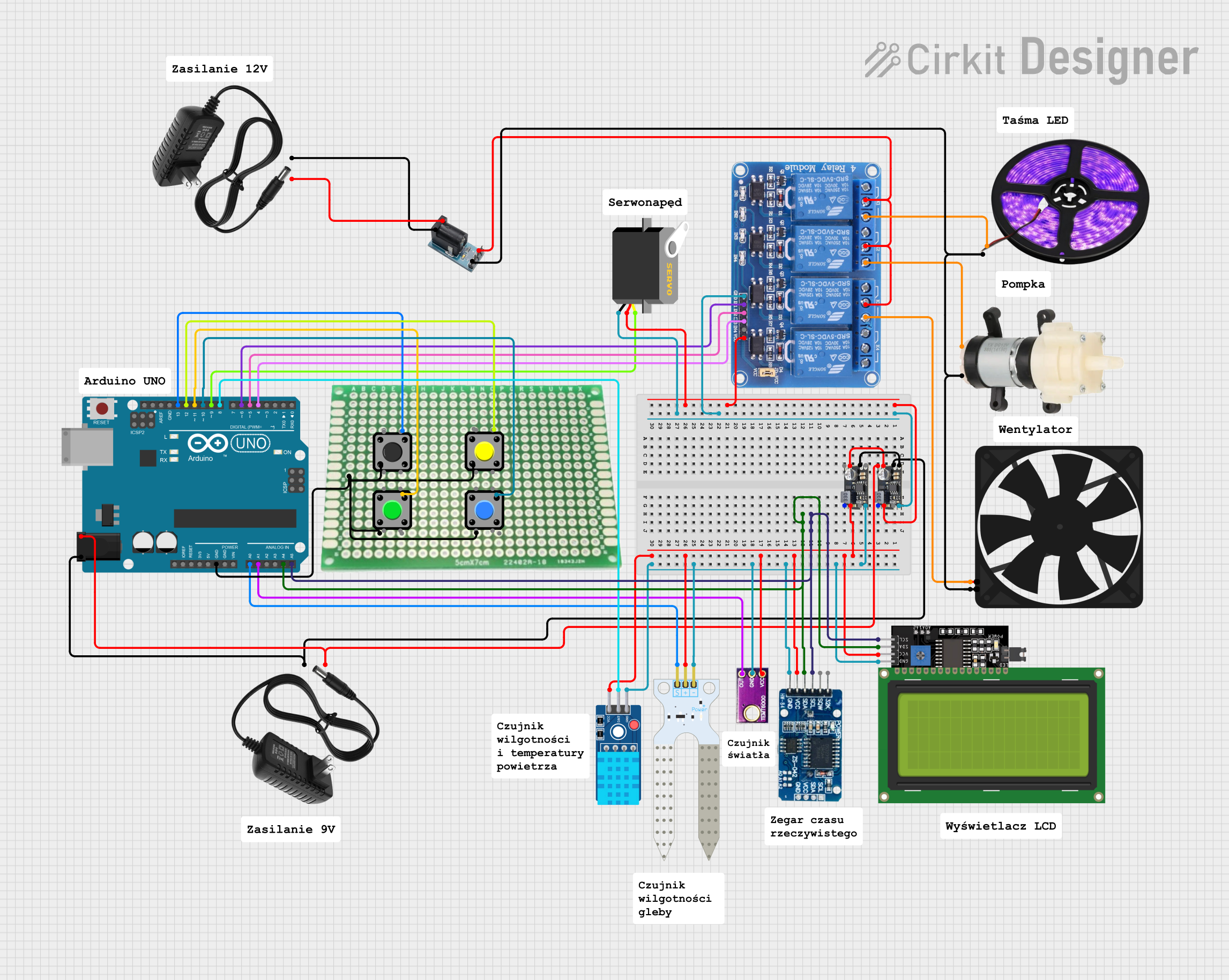
Circuit Documentation
Summary
This document provides a detailed overview of a circuit designed to interface with various sensors, actuators, and modules, including a relay module, servo motor, soil moisture sensor, DHT11 temperature and humidity sensor, ambient light sensor, mini diaphragm water pump, LCD display, and a real-time clock (RTC) module. The circuit is controlled by an Arduino UNO microcontroller, which manages input signals from the sensors and controls the actuators accordingly. The circuit is powered by a 12V power supply, with voltage regulation provided by V100 EY9 modules.
Component List
Relay 4 Channel 5v
- A 4-channel relay module capable of controlling multiple high-power circuits.
Servo
- A servo motor used for precise control of mechanical movement.
Soil Moisture Sensor
- A sensor that measures the moisture level in the soil.
DHT11 Sensor V2
- A sensor that measures temperature and humidity.
Ambient Light Sensor
- A sensor that detects the intensity of ambient light.
Mini Diaphragm Water Pump
- A small pump used for moving water.
12v Power Supply
- A power supply unit that provides 12V DC power.
V100 EY9
- A voltage regulator module that provides stable output voltage.
Arduino UNO
- A microcontroller board based on the ATmega328P.
Gniazdo
- A socket or connector for providing power to the circuit.
LCD Display 20x4 I2C
- A 20x4 character LCD display with an I2C interface.
Fan
- A small fan used for cooling.
LED Light Strips (Violet)
- Violet LED light strips for illumination.
Board
- A generic board, possibly used for mounting components.
Pushbutton
- A momentary pushbutton switch.
Tactile Switch Buttons - 12mm Square
- A tactile switch button for user input.
RTC DS3231
- A real-time clock module for timekeeping.
Wiring Details
Relay 4 Channel 5v
- GND: Connected to system ground.
- IN1, IN2, IN3: Controlled by Arduino UNO digital pins.
- VCC: Powered by V100 EY9 module.
- COM1, COM2, COM3: Connected to Gniazdo positive terminal.
- NO1: Connected to LED Light Strips (Violet) VCC.
- NO2: Connected to Mini Diaphragm Water Pump Positive (+).
- NO3: Connected to Fan 5V.
Servo
- gnd: Connected to system ground.
- vcc: Powered by V100 EY9 module.
- pulse: Controlled by Arduino UNO digital pin D9.
Soil Moisture Sensor
- GND: Connected to system ground.
- VCC: Powered by V100 EY9 module.
- SIG: Signal connected to Arduino UNO analog pin A0.
DHT11 Sensor V2
- GND: Connected to system ground.
- DAT: Data connected to Arduino UNO digital pin D8.
- VCC: Powered by V100 EY9 module.
Ambient Light Sensor
- GND: Connected to system ground.
- OUT: Signal connected to Arduino UNO analog pin A1.
- VCC: Powered by V100 EY9 module.
Mini Diaphragm Water Pump
- Negative (-): Connected to system ground.
- Positive (+): Controlled by Relay 4 Channel 5v NO2.
12v Power Supply
- +: Provides power to V100 EY9 modules and Gniazdo.
- -: Connected to system ground.
V100 EY9
- VINOUT+, VINOUT-: Provide regulated voltage to various components.
- EN: Enabled by Arduino UNO digital pin.
- VIN+, VIN-: Connected to 12v power supply.
Arduino UNO
- A5, A4: Connected to I2C bus (SCL, SDA) for LCD Display and RTC DS3231.
- D6, D5, D4: Control signals for Relay 4 Channel 5v.
- D9: PWM output for Servo.
- A0: Analog input from Soil Moisture Sensor.
- D8: Digital input from DHT11 Sensor V2.
- A1: Analog input from Ambient Light Sensor.
- +, -: Power input from 12v power supply through V100 EY9.
- GND: System ground.
Gniazdo
- +: Connected to 12v power supply positive terminal.
- -: Connected to system ground.
LCD Display 20x4 I2C
- SCL, SDA: I2C communication with Arduino UNO.
- VCC: Powered by V100 EY9 module.
- GND: Connected to system ground.
Fan
- 5V: Controlled by Relay 4 Channel 5v NO3.
- GND: Connected to system ground.
LED Light Strips (Violet)
- VCC: Controlled by Relay 4 Channel 5v NO1.
- GND: Connected to system ground.
RTC DS3231
- SCL, SDA: I2C communication with Arduino UNO.
- VCC: Powered by V100 EY9 module.
- GND: Connected to system ground.
Documented Code
Arduino UNO Code (sketch.ino)
void setup() {
  // put your setup code here, to run once:

}

void loop() {
  // put your main code here, to run repeatedly:

}
Note: The provided code is a template and does not contain any functional code specific to the circuit's operation. It will need to be populated with the necessary setup and loop routines to control the connected components based on the circuit's requirements.