
Circuit Documentation
Summary
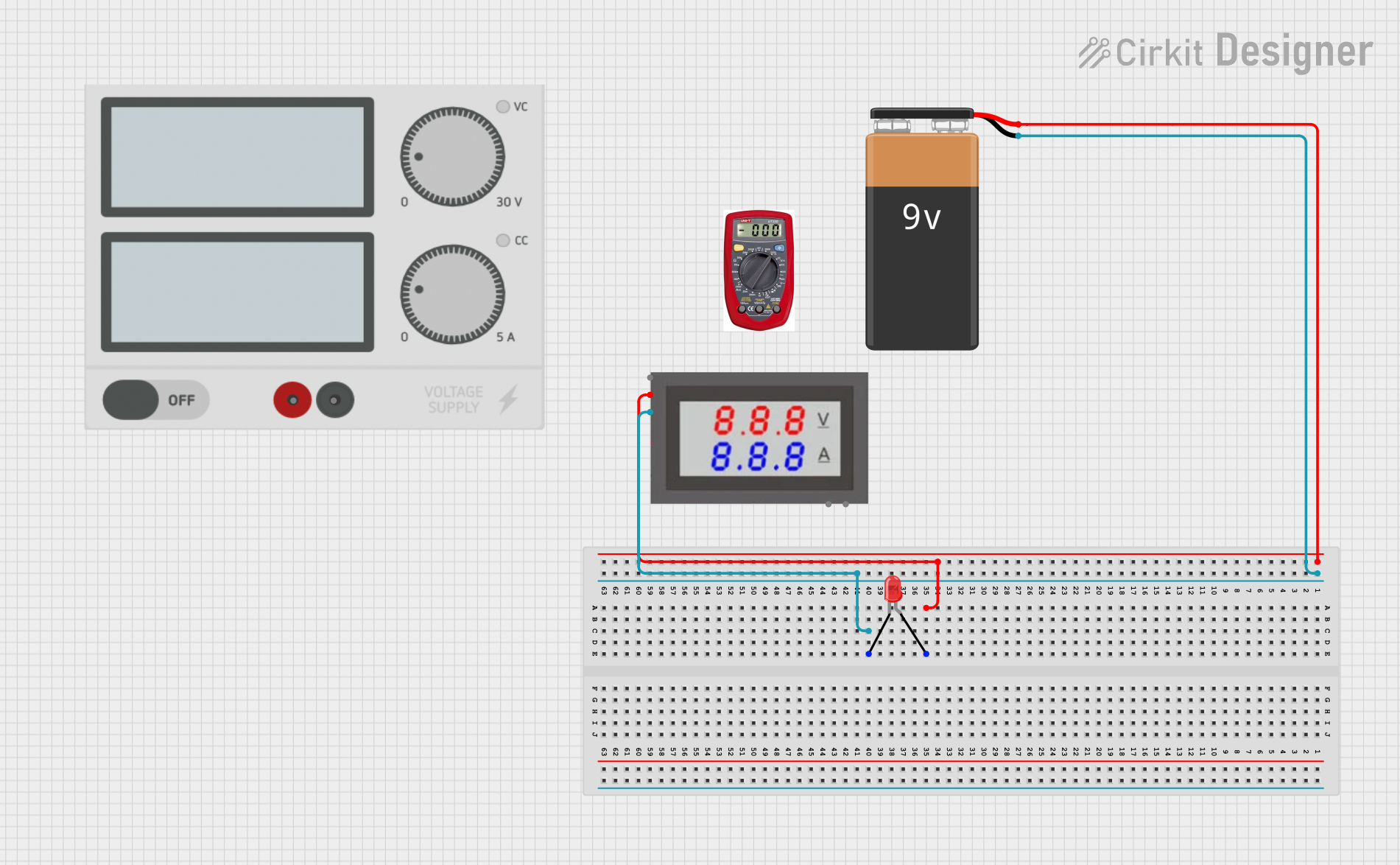
This document provides a detailed description of a simple circuit consisting of a red LED, a 9V battery, and a mini digital volt/ammeter. The circuit is designed to power the LED and measure its voltage and current using the volt/ammeter.
Component List
LED: Two Pin (red)
- Description: A standard red LED with two pins: anode and cathode.
- Pins: cathode, anode
Power Supply
- Description: A generic power supply with positive and negative terminals.
- Pins: +, -
Multimeter
- Description: A device used to measure voltage, current, and resistance.
- Pins: COM, V, A
9V Battery
- Description: A standard 9V battery used as the power source for the circuit.
- Pins: -, +
Mini Digital Volt/Ammeter
- Description: A digital device used to measure voltage and current in the circuit.
- Pins: Gnd, Vin, Vread, Vsupply
Wiring Details
LED: Two Pin (red)
Anode is connected to:
- Vsupply of the Mini Digital Volt/Ammeter
- + of the 9V Battery
Cathode is connected to:
- Gnd of the Mini Digital Volt/Ammeter
- - of the 9V Battery
Power Supply
- + is not connected in this circuit.
- - is not connected in this circuit.
Multimeter
- COM is not connected in this circuit.
- V is not connected in this circuit.
- A is not connected in this circuit.
9V Battery
+ is connected to:
- Anode of the LED
- Vsupply of the Mini Digital Volt/Ammeter
- is connected to:
- Cathode of the LED
- Gnd of the Mini Digital Volt/Ammeter
Mini Digital Volt/Ammeter
Gnd is connected to:
- Cathode of the LED
- - of the 9V Battery
Vin is not connected in this circuit.
Vread is not connected in this circuit.
Vsupply is connected to:
- Anode of the LED
- + of the 9V Battery
Code
There is no embedded code associated with this circuit.
This document provides a comprehensive overview of the circuit, including a summary, detailed component list, wiring details, and code documentation.