
IoT-Enabled Environmental Monitoring System with NUCLEO-F303RE and ESP8266
View and Edit Project In Cirkit Designer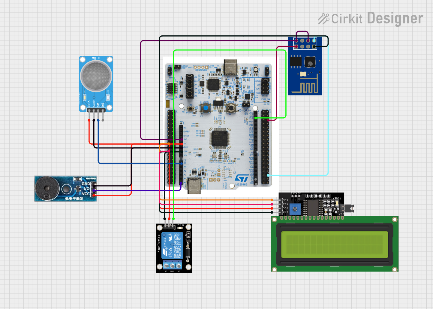
Circuit Documentation
Summary
The circuit in question is designed to interface a NUCLEO-F303RE development board with various peripheral modules including an LCD display, a WiFi module, a buzzer, a relay module, and an MQ-2 gas sensor. The NUCLEO-F303RE board serves as the central processing unit, controlling the peripherals through various communication protocols and GPIO connections. The LCD display is connected via I2C, the ESP8266 WiFi module via UART, the buzzer through a timer pin, the relay module through a GPIO pin, and the MQ-2 sensor through an ADC pin. Power distribution is managed with +3V and +5V lines from the NUCLEO-F303RE board, and a common ground is shared among all components.
Component List
Buzzer Module
- Pins: GND, Vcc, I/O
- Description: An audio signaling device that emits a tone when powered.
KY-019 Relay Module 1 Channel
- Pins: S, 5V, GND, NC, COM, NO
- Description: A relay module capable of switching higher power loads using a low power signal.
NUCLEO-F303RE BOARD
- Pins: SCL_I2C(PA15), SDA_I2C(PB7), USART_1 TX, USART1_RX (PC5), USART_2 RX(PA3), USART_2 TX(PA2), TIM1(PC0), ADC1(PA0), RELAY_IN(PB9), +3V, +5V, GND
- Description: A microcontroller board based on the STM32F303RE MCU, suitable for rapid prototyping.
ESP8266 ESP-01 WiFi Module
- Pins: TXD, CH_PD, RST, VCC, GND, GPIO_2, GPIO_0, RXD
- Description: A compact WiFi module that provides internet connectivity to microcontroller projects.
MQ-2 SENSOR
- Pins: VCC, GND, A0, D0
- Description: A gas sensor used for detecting a wide range of gases including LPG, smoke, and alcohol vapor.
LCD Display 16x4 I2C
- Pins: SCL, SDA, VCC, GND
- Description: A 16x4 character LCD display with an I2C interface for displaying text and characters.
Wiring Details
Buzzer Module
- Vcc: Connected to +5V from NUCLEO-F303RE BOARD
- GND: Connected to GND from NUCLEO-F303RE BOARD
- I/O: Connected to TIM1(PC0) on NUCLEO-F303RE BOARD
KY-019 Relay Module 1 Channel
- S: Connected to RELAY_IN(PB9) on NUCLEO-F303RE BOARD
- 5V: Connected to +5V from NUCLEO-F303RE BOARD
- GND: Connected to GND from NUCLEO-F303RE BOARD
- NC, COM, NO: These are the relay switch pins and are not connected in this net list.
NUCLEO-F303RE BOARD
- I2C Pins: SCL_I2C(PA15) and SDA_I2C(PB7) connected to the corresponding SCL and SDA pins on the LCD Display 16x4 I2C.
- UART Pins: USART_1 TX connected to RXD on ESP8266 ESP-01 WiFi Module, and USART1_RX (PC5) connected to TXD on ESP8266 ESP-01 WiFi Module.
- TIM1(PC0): Connected to I/O on Buzzer Module.
- ADC1(PA0): Connected to A0 on MQ-2 SENSOR.
- RELAY_IN(PB9): Connected to S on KY-019 Relay module 1 channel.
- Power Pins: +3V connected to CH_PD and VCC on ESP8266 ESP-01 WiFi Module. +5V connected to Vcc on Buzzer Module, 5V on KY-019 Relay module 1 channel, VCC on LCD Display 16x4 I2C, and VCC on MQ-2 SENSOR.
- GND: Common ground for all components.
ESP8266 ESP-01 WiFi Module
- TXD: Connected to USART1_RX (PC5) on NUCLEO-F303RE BOARD
- CH_PD and VCC: Connected to +3V from NUCLEO-F303RE BOARD
- GND: Connected to GND from NUCLEO-F303RE BOARD
- RXD: Connected to USART_1 TX on NUCLEO-F303RE BOARD
MQ-2 SENSOR
- VCC: Connected to +5V from NUCLEO-F303RE BOARD
- GND: Connected to GND from NUCLEO-F303RE BOARD
- A0: Connected to ADC1(PA0) on NUCLEO-F303RE BOARD
LCD Display 16x4 I2C
- SCL: Connected to SCL_I2C(PA15) on NUCLEO-F303RE BOARD
- SDA: Connected to SDA_I2C(PB7) on NUCLEO-F303RE BOARD
- VCC: Connected to +5V from NUCLEO-F303RE BOARD
- GND: Connected to GND from NUCLEO-F303RE BOARD
Documented Code
No code was provided for the microcontrollers in the circuit. Therefore, this section is left blank until the relevant code is supplied. The code would typically include initialization and control routines for the I2C and UART interfaces, ADC configuration, timer setup for the buzzer, and GPIO control for the relay module.