
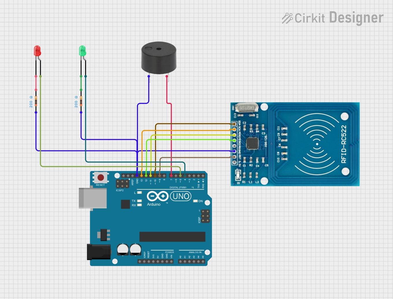
Circuit Documentation
Summary of the Circuit
This circuit is designed to implement a vehicle detection system using RFID technology. It consists of multiple Arduino UNO microcontrollers, an RFID-RC522 module, a buzzer, LEDs, and resistors. The RFID reader detects the presence of RFID tags, which are used to represent vehicles in this context. Upon detection, the system activates a buzzer and a green LED as an indication of vehicle presence. If no vehicle is detected, a red LED is illuminated. The circuit uses digital I/O pins for interfacing with the RFID module and the indicators (buzzer and LEDs).
Component List
Microcontrollers
- Arduino UNO: A microcontroller board based on the ATmega328P. It has 14 digital input/output pins, 6 analog inputs, a 16 MHz quartz crystal, a USB connection, a power jack, an ICSP header, and a reset button.
RFID Module
- RFID-RC522: An RFID reader/writer module that operates at 13.56 MHz. It communicates with the microcontroller via SPI and has pins for power (VCC), reset (RST), ground (GND), interrupt request (IRQ), master-in slave-out (MISO), master-out slave-in (MOSI), serial clock (SCK), and serial data (SDA).
Indicators
- Buzzer: An electronic buzzer that can be used to create audio signals.
- LED: Two Pin (green): A green LED used to indicate vehicle detection.
- LED: Two Pin (red): A red LED used to indicate the absence of a vehicle.
Resistors
- Resistor: A 200 Ohm resistor used to limit current to the LEDs and protect them from damage.
Wiring Details
Arduino UNO
- GND: Connected to the ground pins of the buzzer, RFID-RC522, and both resistors.
- D13: Connected to the SCK pin of the RFID-RC522.
- D12: Connected to the MISO pin of the RFID-RC522.
- D11: Connected to the MOSI pin of the RFID-RC522.
- D10: Connected to the SDA pin of the RFID-RC522.
- D9: Connected to the RST pin of the RFID-RC522.
- D7: Connected to the buzzer.
- D5: Connected to the anode of the red LED through a 200 Ohm resistor.
- D4: Connected to the anode of the green LED through a 200 Ohm resistor.
Buzzer
- PIN: Connected to D7 on the Arduino UNO.
- GND: Connected to the ground net.
RFID-RC522
- VCC (3.3V): Connected to a 3.3V power source.
- RST: Connected to D9 on the Arduino UNO.
- GND: Connected to the ground net.
- IRQ: Not connected in this circuit.
- MISO: Connected to D12 on the Arduino UNO.
- MOSI: Connected to D11 on the Arduino UNO.
- SCK: Connected to D13 on the Arduino UNO.
- SDA: Connected to D10 on the Arduino UNO.
LEDs
- Green LED: Anode connected to D4 on the Arduino UNO through a 200 Ohm resistor. Cathode connected to the ground net.
- Red LED: Anode connected to D5 on the Arduino UNO through a 200 Ohm resistor. Cathode connected to the ground net.
Resistors
- 200 Ohm Resistor: One end connected to the anode of the green LED, the other end connected to D4 on the Arduino UNO.
- 200 Ohm Resistor: One end connected to the anode of the red LED, the other end connected to D5 on the Arduino UNO.
Documented Code
Arduino UNO (Vehicle Detection System)
/*
 * Vehicle Detection System using RFID
 * This system uses an RFID reader to detect vehicles and triggers a buzzer
 * and green LED when a vehicle is detected. If no vehicle is detected, the
 * red LED will glow.
 */

#include <SPI.h>
#include <MFRC522.h>

// Pin definitions
#define RST_PIN 9
#define SS_PIN 10
#define GREEN_LED_PIN 4
#define RED_LED_PIN 5
#define BUZZER_PIN 7

// Initialize RFID
MFRC522 rfid(SS_PIN, RST_PIN);

void setup() {
  // Initialize serial communication
  Serial.begin(9600);

  // Initialize RFID
  SPI.begin();
  rfid.PCD_Init();

  // Initialize pins
  pinMode(GREEN_LED_PIN, OUTPUT);
  pinMode(RED_LED_PIN, OUTPUT);
  pinMode(BUZZER_PIN, OUTPUT);

  // Welcome message
  Serial.println("Vehicle Detection System Ready");
}

void loop() {
  // Check for RFID card
  if (rfid.PICC_IsNewCardPresent() && rfid.PICC_ReadCardSerial()) {
    // Vehicle detected
    Serial.println("Vehicle Detected");
    triggerAlert();
    rfid.PICC_HaltA();
  } else {
    // No vehicle detected
    digitalWrite(GREEN_LED_PIN, LOW);
    digitalWrite(RED_LED_PIN, HIGH);
  }
}

void triggerAlert() {
  // Turn on green LED
  digitalWrite(GREEN_LED_PIN, HIGH);
  digitalWrite(RED_LED_PIN, LOW);

  // Activate buzzer
  digitalWrite(BUZZER_PIN, HIGH);
  delay(1000);
  digitalWrite(BUZZER_PIN, LOW);

  // Turn off green LED
  digitalWrite(GREEN_LED_PIN, LOW);
}
(Note: The code provided is for one of the Arduino UNO microcontrollers in the circuit. The other microcontrollers' code is not included as it was not provided or was empty.)