Cirkit Designer
Your all-in-one circuit design IDE
Home /
Project Documentation
Solar-Powered Battery Charging Circuit with LED Indicator
Circuit Documentation
Summary
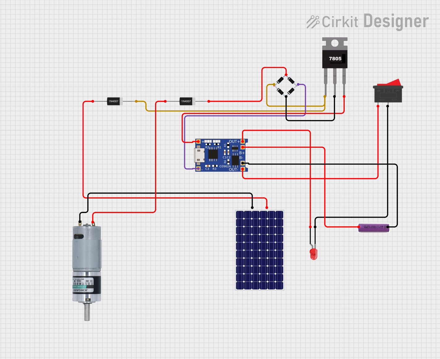
The circuit in question appears to be a charging and power management system designed to charge a 3.7V battery using a solar panel and to provide a regulated 5V output. It includes a TP4056 lithium battery charger module for charging the battery, a rocker switch for controlling the power flow, a bridge rectifier for converting AC to DC from the solar panel, a 7805 voltage regulator for providing a stable 5V output, and a red LED as an indicator. Additionally, there are diodes for protection and a motor connected to the system.
Component List
Rocker Switch
- A simple on-off switch used to control the power flow in the circuit.
3.7V Battery
- The energy storage component of the circuit, which is charged by the TP4056 module.
TP4056
- A lithium battery charger module that charges the battery and provides power to the circuit.
MRB Planetary Gearbox Motor
- A motor that is likely used as a load or actuator in the circuit.
1N4007 Rectifier Diode (x2)
- Diodes used for protection against reverse polarity and to ensure current flows in one direction.
Solar Panel
- The energy harvesting component that provides power to charge the battery via the TP4056 module.
Bridge Rectifier
- Converts the alternating current (AC) from the solar panel to direct current (DC) for the circuit.
LED: Two Pin (red)
- An indicator light that could be used to show the status of the circuit, such as power on or charging.
7805 Voltage Regulator
- A component that provides a stable 5V output from a higher voltage input.
Wiring Details
Rocker Switch
- Pin 1 is connected to the OUT- of the TP4056.
- Pin 2 is connected to the cathode of the red LED.
3.7V Battery
- Positive pin (+) is connected to the B+ of the TP4056.
- Negative pin (-) is connected to the B- of the TP4056.
TP4056
- OUT- is connected to Pin 1 of the Rocker Switch.
- B+ is connected to the positive pin (+) of the 3.7V Battery.
- B- is connected to the negative pin (-) of the 3.7V Battery.
- OUT+ is connected to the anode of the red LED.
- IN- is connected to the source_out- of the Bridge Rectifier.
- IN+ is connected to the Vout of the 7805 Voltage Regulator.
MRB Planetary Gearbox Motor
- Positive pin (+) is connected to the anode of a 1N4007 Rectifier Diode.
- Negative pin (-) is connected to the negative pin (-) of the Solar Panel.
1N4007 Rectifier Diode
- One diode has its cathode connected to the source_out+ of the Bridge Rectifier and its anode connected to the positive pin (+) of the Solar Panel.
- The other diode has its anode connected to the positive pin (+) of the MRB Planetary Gearbox Motor and its cathode connected to the source_in+ of the Bridge Rectifier.
Solar Panel
- Positive pin (+) is connected to the anode of a 1N4007 Rectifier Diode.
- Negative pin (-) is connected to the negative pin (-) of the MRB Planetary Gearbox Motor.
Bridge Rectifier
- Source_in- is connected to the Gnd of the 7805 Voltage Regulator.
- Source_out- is connected to the IN- of the TP4056.
- Source_out+ is connected to the Vin of the 7805 Voltage Regulator and the cathode of a 1N4007 Rectifier Diode.
- Source_in+ is connected to the cathode of another 1N4007 Rectifier Diode.
LED: Two Pin (red)
- Cathode is connected to Pin 2 of the Rocker Switch.
- Anode is connected to the OUT+ of the TP4056.
7805 Voltage Regulator
- Vin is connected to the source_out+ of the Bridge Rectifier.
- Gnd is connected to the Source_in- of the Bridge Rectifier.
- Vout is connected to the IN+ of the TP4056.
Documented Code
There is no embedded code provided for any microcontrollers in this circuit. If there were microcontrollers and associated code, this section would detail the functionality and provide code annotations.