Arduino Mega 2560-Controlled Robotic Vehicle with Ultrasonic Obstacle Detection and Bluetooth Connectivity
Circuit Documentation
Summary
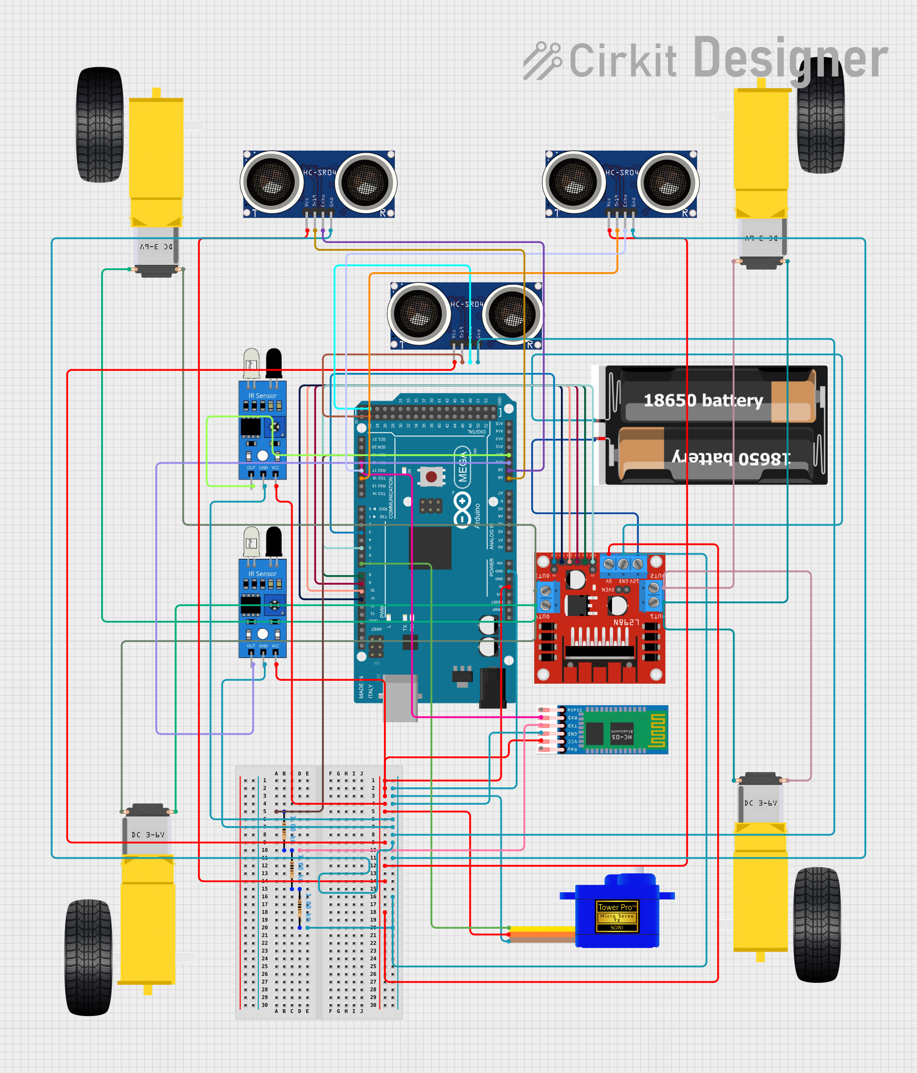
This circuit is designed to interface various sensors, actuators, and a communication module with an Arduino Mega 2560 microcontroller. It includes ultrasonic sensors (HC-SR04) for distance measurement, IR sensors for object detection, a DC motor driver (L298N) to control gearmotors for wheels, a servomotor (SG90) for precise angular movement, and a Bluetooth module (HC-05) for wireless communication. The power supply is provided by two 18650 batteries, and resistors are used for voltage/current adjustments and signal conditioning.
Component List
Sensors
- Ultrasonic Sensor (HC-SR04): Used for measuring distances by emitting ultrasonic waves and measuring the time taken for the echo to return.
- IR Sensor: Detects the presence of objects based on infrared light reflection.
Actuators
- Gearmotor DC Wheels (Left and Right): Provides the driving force for the wheels, allowing the system to move.
- Servomotor (SG90): A small rotary actuator that allows for precise control of angular position.
Communication Module
- Bluetooth Module (HC-05): Enables wireless communication with other devices via Bluetooth.
Motor Driver
- L298N DC Motor Driver: Controls the direction and speed of DC motors.
Power Supply
- 2x 18650 Batteries: Provides the necessary power to the circuit.
Microcontroller
- Arduino Mega 2560: The main controller that interfaces with all the components, runs the embedded code, and processes sensor data.
Resistors
- 1k Ohm Resistors: Used for current limiting and voltage division in the circuit.
Wiring Details
Ultrasonic Sensor (HC-SR04)
- VCC: Connected to 5V power supply from Arduino Mega 2560.
- GND: Connected to the common ground.
- TRIG: Connected to digital pins on Arduino Mega 2560 for triggering the ultrasonic pulse.
- ECHO: Connected to digital pins on Arduino Mega 2560 for receiving the echo signal.
IR Sensor
- VCC: Connected to 5V power supply from Arduino Mega 2560.
- GND: Connected to the common ground.
- OUT: Connected to analog pins on Arduino Mega 2560 for object detection signal.
Gearmotor DC Wheels (Left and Right)
- PIN1 & PIN2: Connected to the outputs of the L298N motor driver to control the motion of the wheels.
Servomotor (SG90)
- SIG: Connected to a PWM pin on Arduino Mega 2560 for control signal.
- VCC: Connected to 5V power supply from Arduino Mega 2560.
- GND: Connected to the common ground.
Bluetooth Module (HC-05)
- VCC: Connected to 5V power supply from Arduino Mega 2560.
- GND: Connected to the common ground.
- TXD: Connected to RX pin on Arduino Mega 2560 for transmitting data.
- RXD: Connected to TX pin on Arduino Mega 2560 for receiving data.
L298N DC Motor Driver
- OUT1, OUT2, OUT3, OUT4: Connected to gearmotor wheels.
- 12V: Connected to the 18650 batteries for motor power supply.
- 5V: Connected to 5V power supply from Arduino Mega 2560.
- GND: Connected to the common ground.
- ENA, ENB: Connected to PWM pins on Arduino Mega 2560 for speed control.
- IN1, IN2, IN3, IN4: Connected to digital pins on Arduino Mega 2560 for direction control.
2x 18650 Batteries
- VCC: Provides power to the L298N motor driver.
- GND: Connected to the common ground.
Resistors (1k Ohm)
- Between Arduino Mega 2560 and HC-05: Used for voltage level shifting for the TX/RX lines between the Arduino and the Bluetooth module.
Documented Code
Arduino Mega 2560
void setup() {
  // put your setup code here, to run once:

}

void loop() {
  // put your main code here, to run repeatedly:

}
Filename: sketch.ino
Note: The provided code is a template and does not contain any functional code. It needs to be populated with the logic to control and interface with the components based on the requirements of the application.