Cirkit Designer
Your all-in-one circuit design IDE
Home /
Project Documentation
Battery-Powered Motor Control with MQ-3 Sensor and Buzzer Alert
Circuit Documentation
Summary
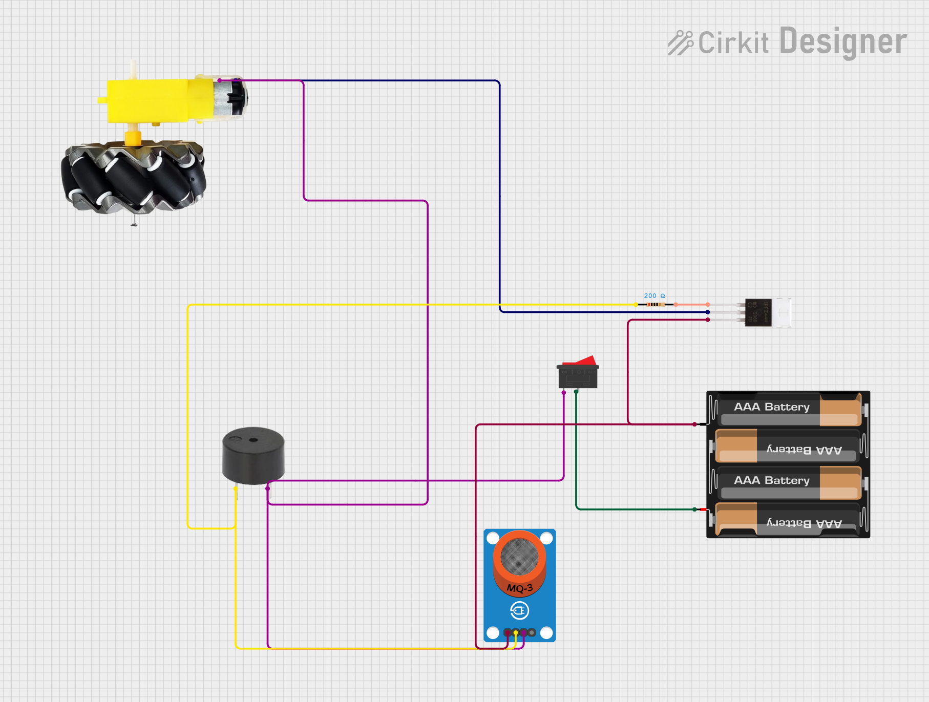
This document provides a detailed overview of a circuit that includes a motor and wheels, an IRFZ44N MOSFET, an MQ-3 gas sensor, a buzzer, a rocker switch, a 4 x AAA battery mount, and a resistor. The circuit is designed to control the motor and wheels based on the input from the MQ-3 gas sensor, with additional functionalities provided by the buzzer and the rocker switch.
Component List
Motor and Wheels
- Pins: VCC, GND
- Description: Motor and wheels assembly for movement.
- Purpose: Provides mechanical movement.
IRFZ44N
- Pins: Gate, Drain, Source
- Description: N-channel MOSFET.
- Purpose: Acts as a switch to control the motor and wheels.
MQ-3 Breakout
- Pins: VCC, GND, DO, AO
- Description: Gas sensor module.
- Purpose: Detects gas levels and provides digital and analog outputs.
Buzzer
- Pins: PIN, GND
- Description: Audio signaling device.
- Purpose: Provides audible alerts.
Rocker Switch
- Pins: 1, 2
- Description: On/Off switch.
- Purpose: Controls the power supply to the circuit.
4 x AAA Battery Mount
- Pins: +, -
- Description: Battery holder for four AAA batteries.
- Purpose: Provides power to the circuit.
Resistor
- Pins: pin1, pin2
- Description: 200 Ohms resistor.
- Purpose: Limits current flow.
Wiring Details
Motor and Wheels
- VCC: Connected to the Drain of the IRFZ44N MOSFET.
- GND: Connected to the GND of the MQ-3 Breakout, the GND of the Buzzer, and pin 1 of the Rocker Switch.
IRFZ44N
- Gate: Connected to pin2 of the Resistor.
- Drain: Connected to the VCC of the Motor and Wheels.
- Source: Connected to the negative terminal of the 4 x AAA Battery Mount and the VCC of the MQ-3 Breakout.
MQ-3 Breakout
- VCC: Connected to the Source of the IRFZ44N MOSFET.
- GND: Connected to the GND of the Buzzer, the GND of the Motor and Wheels, and pin 1 of the Rocker Switch.
- DO: Connected to pin 1 of the Rocker Switch.
- AO: Not connected in this circuit.
Buzzer
- PIN: Connected to pin1 of the Resistor.
- GND: Connected to the GND of the MQ-3 Breakout, the GND of the Motor and Wheels, and pin 1 of the Rocker Switch.
Rocker Switch
- Pin 1: Connected to the GND of the MQ-3 Breakout, the GND of the Buzzer, and the GND of the Motor and Wheels.
- Pin 2: Connected to the positive terminal of the 4 x AAA Battery Mount.
4 x AAA Battery Mount
- Positive (+): Connected to pin 2 of the Rocker Switch.
- Negative (-): Connected to the Source of the IRFZ44N MOSFET and the VCC of the MQ-3 Breakout.
Resistor
- Pin 1: Connected to the PIN of the Buzzer.
- Pin 2: Connected to the Gate of the IRFZ44N MOSFET.
Code
There is no microcontroller code provided for this circuit.
This document provides a comprehensive overview of the circuit, including a summary, detailed component list, wiring details, and code documentation.