ESP8266 NodeMCU-Based Environmental Monitoring and Proximity Detection System
Circuit Documentation
Summary
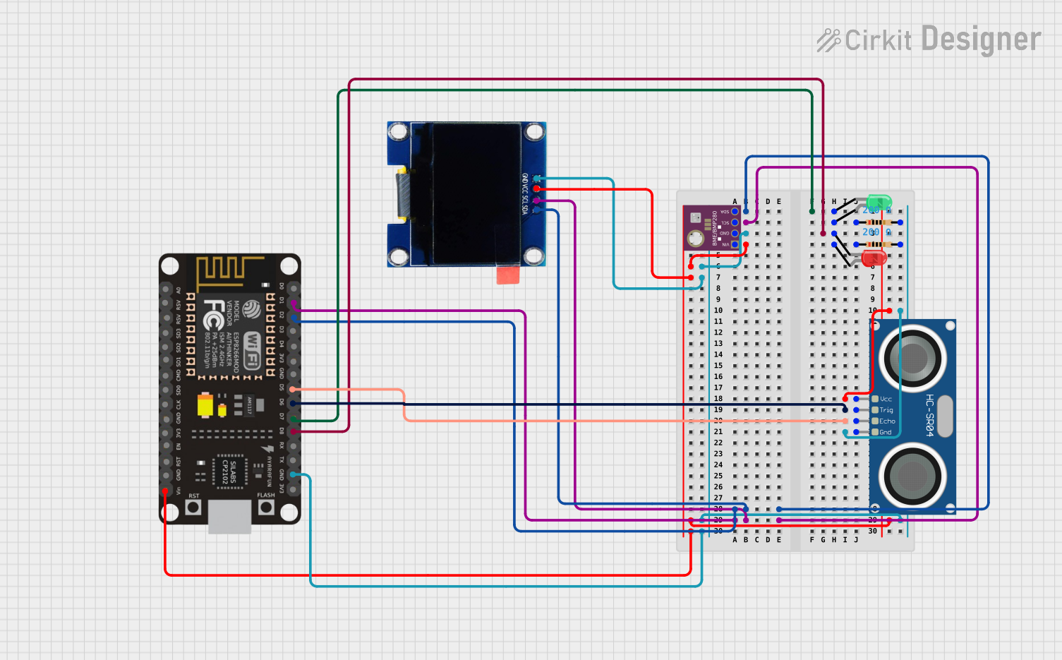
The circuit in question is designed to interface an ESP8266 NodeMCU microcontroller with a variety of sensors and output devices. The sensors include a BME/BMP280 for atmospheric measurements and an HC-SR04 Ultrasonic Sensor for distance measurement. The output devices are two LEDs (one red and one green) and an OLED 1.3" display for visual feedback. The circuit utilizes I2C communication for the BME/BMP280 and OLED display, and GPIO pins for controlling the ultrasonic sensor and LEDs. The LEDs are connected through resistors to limit the current flow.
Component List
ESP8266 NodeMCU
- Microcontroller with WiFi capability.
- Pins: D0, D1, D2, D3, D4, 3V3, GND, D5, D6, D7, D8, RX, TX, A0, RSV, SD3, SD2, SD1, CMD, SD0, CLK, EN, RST, VIN.
BME/BMP280
- Environmental sensor measuring temperature, pressure, and humidity.
- Pins: GND, SCL, SDA, VIN.
HC-SR04 Ultrasonic Sensor
- Sensor for measuring distance via ultrasonic waves.
- Pins: VCC, TRIG, ECHO, GND.
LED: Two Pin (red)
- Red indicator LED.
- Pins: cathode, anode.
LED: Two Pin (green)
- Green indicator LED.
- Pins: cathode, anode.
Resistor (200 Ohms)
- Current limiting resistor for LED protection.
- Pins: pin1, pin2.
OLED 1.3"
- Small display for visual output.
- Pins: GND, VCC, SCL, SDA.
Wiring Details
ESP8266 NodeMCU
- D1 (SCL) connected to BME/BMP280 SCL and OLED SCL.
- D2 (SDA) connected to BME/BMP280 SDA and OLED SDA.
- D5 connected to HC-SR04 ECHO.
- D6 connected to HC-SR04 TRIG.
- D7 connected to Green LED cathode.
- D8 connected to Red LED cathode.
- GND connected to common ground.
- VIN connected to common power supply.
BME/BMP280
- SCL connected to ESP8266 NodeMCU D1.
- SDA connected to ESP8266 NodeMCU D2.
- GND connected to common ground.
- VIN connected to common power supply.
HC-SR04 Ultrasonic Sensor
- VCC connected to common power supply.
- TRIG connected to ESP8266 NodeMCU D6.
- ECHO connected to ESP8266 NodeMCU D5.
- GND connected to common ground.
LED: Two Pin (red)
- Cathode connected to ESP8266 NodeMCU D8.
- Anode connected to one terminal of a 200 Ohm resistor.
LED: Two Pin (green)
- Cathode connected to ESP8266 NodeMCU D7.
- Anode connected to one terminal of a 200 Ohm resistor.
Resistor (200 Ohms)
- One terminal connected to the anode of the red LED.
- The other terminal connected to common ground.
Resistor (200 Ohms)
- One terminal connected to the anode of the green LED.
- The other terminal connected to common ground.
OLED 1.3"
- SCL connected to ESP8266 NodeMCU D1.
- SDA connected to ESP8266 NodeMCU D2.
- GND connected to common ground.
- VCC connected to common power supply.
Documented Code
No code has been provided for the microcontroller. The documentation of the code would typically include setup and loop functions for an Arduino-based microcontroller like the ESP8266 NodeMCU, along with any necessary functions for sensor readings, data processing, and output control.