
Arduino-Controlled Ultrasonic Sensor with Servo and LED Indicator
View and Edit Project In Cirkit Designer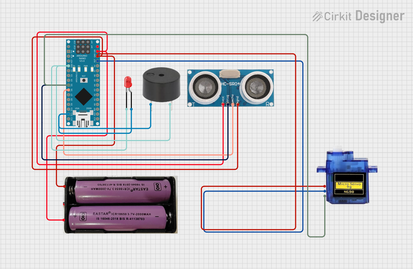
Circuit Documentation
Summary
This circuit integrates various components controlled by two Arduino Nano microcontrollers. It features a micro servo motor, an ultrasonic sensor, a red LED, a buzzer, and a 7.4V power supply. The circuit is designed to interact with the environment using the ultrasonic sensor and to provide visual and auditory feedback through the LED and buzzer, respectively. The micro servo is controlled via PWM signal from one of the Arduino Nanos.
Component List
Micro servo 9G
- Description: A small and lightweight servo motor for precise angular movement.
- Pins: GND, +5V, PWM
Ultrasonic Sensor
- Description: A sensor that measures distance by emitting ultrasonic waves and measuring the time taken for the echo to return.
- Pins: +VCC, Trigger, Echo, GND
LED: Two Pin (red)
- Description: A basic red LED for visual signaling.
- Pins: cathode, anode
7.4V Power Supply
- Description: Provides power to the circuit.
- Pins: + (positive), - (negative)
Arduino Nano (x2)
- Description: A compact microcontroller board based on the ATmega328P, used for controlling the components in the circuit.
- Pins: D1/TX, D0/RX, RESET, GND, D2 to D13, VIN, 5V, A0 to A7, AREF, 3V3
Buzzer
- Description: An audible signaling device.
- Pins: PIN, GND
Wiring Details
Micro servo 9G
- GND: Connected to 7.4V Power Supply (-)
- +5V: Connected to Arduino Nano (5V)
- PWM: Connected to Arduino Nano (D5)
Ultrasonic Sensor
- +VCC: Connected to 7.4V Power Supply (+)
- Trigger: Connected to Arduino Nano (D6)
- Echo: Connected to Arduino Nano (D7)
- GND: Connected to 7.4V Power Supply (-)
LED: Two Pin (red)
- Cathode: Connected to Arduino Nano (GND)
- Anode: Connected to Arduino Nano (D11/MOSI)
7.4V Power Supply
- +: Connected to Arduino Nano (VIN) and Ultrasonic Sensor (+VCC)
- -: Connected to Arduino Nano (GND), Micro servo 9G (GND), and Ultrasonic Sensor (GND)
Arduino Nano
- GND: Shared with LED, Buzzer, Micro servo 9G, and Ultrasonic Sensor
- 5V: Connected to Micro servo 9G (+5V)
- VIN: Connected to 7.4V Power Supply (+)
- D5: Connected to Micro servo 9G (PWM)
- D6: Connected to Ultrasonic Sensor (Trigger)
- D7: Connected to Ultrasonic Sensor (Echo)
- D11/MOSI: Connected to LED (Anode)
Buzzer
- PIN: Connected to Arduino Nano (D11/MOSI)
- GND: Connected to Arduino Nano (GND)
Documented Code
Arduino Nano (First Instance)
void setup() {
  // put your setup code here, to run once:

}

void loop() {
  // put your main code here, to run repeatedly:

}
Filename: sketch.ino
Arduino Nano (Second Instance)
void setup() {
  // put your setup code here, to run once:

}

void loop() {
  // put your main code here, to run repeatedly:

}
Filename: sketch.ino
Note: The code provided for both Arduino Nano instances is a template and does not contain any functional code specific to the circuit's operation. The actual implementation should be added to the setup() and loop() functions as per the circuit's requirements.