
Arduino-Controlled Automated Plant Watering System with Soil Moisture Sensing and Temperature Monitoring
View and Edit Project In Cirkit Designer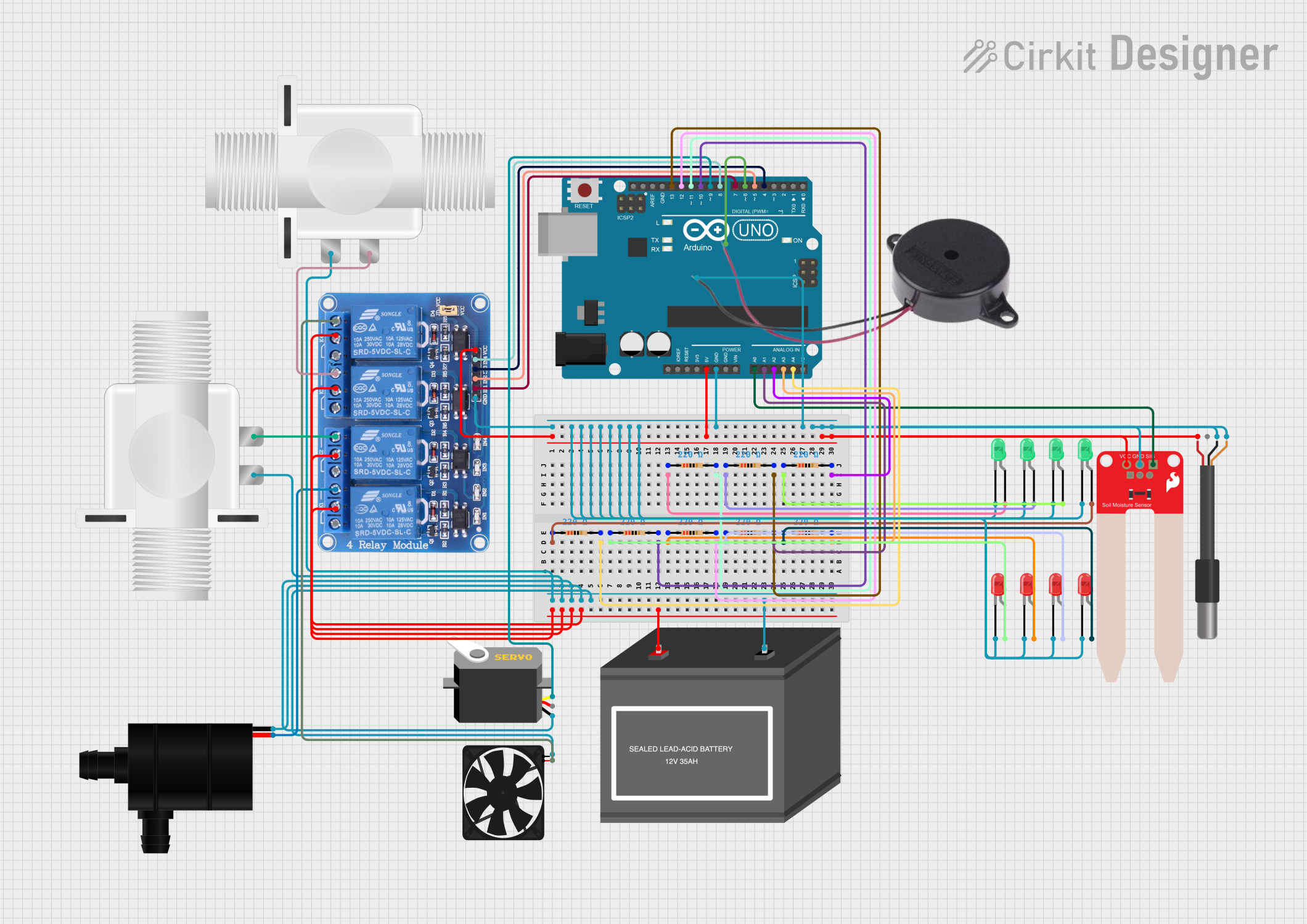
Circuit Documentation
Summary
This circuit is designed to monitor soil moisture levels and control a water pump and solenoid valves for irrigation purposes. It includes temperature sensing, visual indicators (LEDs), and an audible alarm (buzzer). The system is controlled by an Arduino UNO microcontroller, which manages sensor inputs and actuator outputs. The circuit is powered by a 12V battery and includes a relay module to control high-power devices.
Component List
- SparkFun Soil Moisture Sensor: Measures the moisture level in the soil.
- Plastic Solenoid Valve: Controls the flow of water when activated.
- 12V Battery (mini): Provides power to the circuit.
- Buzzer: Emits an audible alarm when triggered.
- Servo: A small motor that can be precisely controlled.
- LED (green): Visual indicator for various statuses.
- LED (red): Visual indicator for alerts or different statuses.
- DS18B20 1-Wire Temperature Sensor Probe Cable: Measures temperature.
- Relay 4 Channel 5v: Allows the Arduino to control high-power devices.
- Arduino UNO: The main microcontroller board that controls the circuit.
- Water Pump: Pumps water for irrigation.
- Fan: Provides air circulation.
- Resistor (220 Ohms): Limits current to protect LEDs.
Wiring Details
SparkFun Soil Moisture Sensor
- VCC: Connected to 5V from the Arduino UNO.
- GND: Connected to GND.
- SIG: Connected to A0 on the Arduino UNO.
Plastic Solenoid Valve
- pin1: Connected to the normally open (NO) contacts of the relay module.
- pin2: Connected to the 12V battery negative terminal.
12V Battery (mini)
- +: Connected to the common (COM) contacts of the relay module.
- -: Connected to GND.
Buzzer
- POSITIVE: Connected to D6 on the Arduino UNO.
- NEGATIVE: Connected to GND.
Servo
- gnd: Connected to GND.
- vcc: Connected to 5V from the Arduino UNO.
- pulse: Connected to D9 on the Arduino UNO.
LED (green)
- cathode: Connected to GND through a 220 Ohm resistor.
- anode: Connected to various digital pins on the Arduino UNO (D11, D13, A2, A4).
LED (red)
- cathode: Connected to GND through a 220 Ohm resistor.
- anode: Connected to various digital pins on the Arduino UNO (D10, A1, A3).
DS18B20 1-Wire Temperature Sensor Probe Cable
- shield: Connected to GND.
- GND: Connected to GND.
- DQ: Data line not specified in the net list.
- VDD: Connected to 5V from the Arduino UNO.
Relay 4 Channel 5v
- GND: Connected to GND.
- IN1, IN2, IN3, IN4: Connected to D7, D5, D4, D8 on the Arduino UNO respectively.
- VCC: Connected to 5V from the Arduino UNO.
- COM1, COM2, COM3, COM4: All connected to the 12V battery positive terminal.
- NO1, NO2, NO3, NO4: Connected to the water pump, solenoid valves, and fan.
Arduino UNO
- 5V: Provides power to the 5V components in the circuit.
- GND: Common ground for the circuit.
- Digital and Analog pins: Connected to various components as specified above.
Water Pump
- VCC: Connected to the normally open (NO) contact of the relay module.
- GND: Connected to GND.
Fan
- 5V: Connected to the normally open (NO) contact of the relay module.
- GND: Connected to GND.
Resistor (220 Ohms)
- pin1: Connected to the anode of an LED.
- pin2: Connected to a digital or analog pin on the Arduino UNO.
Documented Code
Arduino UNO Code (sketch.ino)
void setup() {
  // put your setup code here, to run once:

}

void loop() {
  // put your main code here, to run repeatedly:

}
Note: The provided code is a template and does not include specific functionality. It needs to be completed with the logic for reading sensors, controlling actuators, and implementing the desired behavior of the circuit.