Cirkit Designer
Your all-in-one circuit design IDE
Home /
Project Documentation
ESP32C3-Based Soil Monitoring System with RS485 Communication
Circuit Documentation
Summary
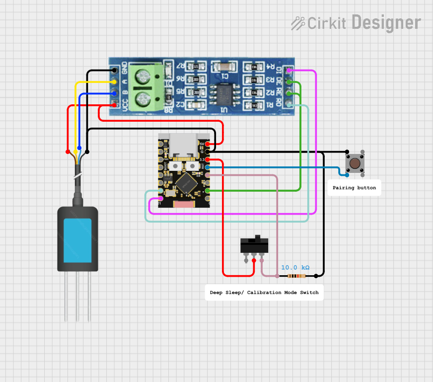
This circuit integrates an ESP32C3 Supermini microcontroller with an RS485 transceiver module, an NPK Soil Sensor, a pushbutton, and a toggle switch. The circuit is designed to interface with the soil sensor using RS485 communication, facilitated by the ESP32C3 Supermini. The pushbutton and toggle switch are used for input, and a resistor is included for pull-up or pull-down purposes.
Component List
ESP32C3 Supermini
- Description: A compact microcontroller module based on the ESP32-C3 chip, featuring Wi-Fi and Bluetooth capabilities along with a variety of GPIO pins.
- Pins: GPIO05, GPIO06, GPIO07, GPIO08, GPIO09, GPIO10, GPIO20, GPIO21, GPIO00, GPIO01, GPIO02, GPIO03, GPIO04, 3.3V, GND, +5V
RS485 Transceiver Module
- Description: A module used for RS485 serial communication, which allows for long-distance and differential signal transmission.
- Pins: VCC, RO, RE, GND, B, A, DE, DI
NPK Soil Sensor
- Description: A sensor used to measure the nitrogen, phosphorus, and potassium content in the soil.
- Pins: 12V DC, A, B, GND
Pushbutton
- Description: A simple pushbutton switch used for user input.
- Pins: Pin 3 (out), Pin 4 (out), Pin 1 (in), Pin 2 (in)
Toggle Switch
- Description: A switch that can maintain its state either in on or off position.
- Pins: L1, COM, L2
Resistor (10 kOhms)
- Description: A passive two-terminal electrical component that implements electrical resistance as a circuit element.
- Pins: pin1, pin2
- Resistance: 10,000 Ohms
Wiring Details
ESP32C3 Supermini
- GPIO20 connected to RS485 RO
- GPIO21 connected to RS485 DI
- GPIO01 connected to RS485 RE and DE
- GPIO03 connected to Toggle Switch L2 and Resistor pin1
- GPIO04 connected to Pushbutton Pin 2 (in)
- 3.3V connected to Toggle Switch COM
- GND connected to RS485 GND, NPK Soil Sensor GND, Pushbutton Pin 1 (in), and Resistor pin2
- +5V connected to RS485 VCC and NPK Soil Sensor 12V DC
RS485 Transceiver Module
- RO connected to ESP32C3 Supermini GPIO20
- DI connected to ESP32C3 Supermini GPIO21
- RE and DE connected to ESP32C3 Supermini GPIO01
- GND connected to ESP32C3 Supermini GND, NPK Soil Sensor GND, Pushbutton Pin 1 (in), and Resistor pin2
- VCC connected to ESP32C3 Supermini +5V and NPK Soil Sensor 12V DC
- B connected to NPK Soil Sensor B
- A connected to NPK Soil Sensor A
NPK Soil Sensor
- 12V DC connected to ESP32C3 Supermini +5V and RS485 VCC
- A connected to RS485 A
- B connected to RS485 B
- GND connected to ESP32C3 Supermini GND, RS485 GND, Pushbutton Pin 1 (in), and Resistor pin2
Pushbutton
- Pin 3 (out) (Not connected)
- Pin 4 (out) (Not connected)
- Pin 1 (in) connected to ESP32C3 Supermini GND, RS485 GND, NPK Soil Sensor GND, and Resistor pin2
- Pin 2 (in) connected to ESP32C3 Supermini GPIO04
Toggle Switch
- L1 (Not connected)
- COM connected to ESP32C3 Supermini 3.3V
- L2 connected to ESP32C3 Supermini GPIO03 and Resistor pin1
Resistor (10 kOhms)
- pin1 connected to ESP32C3 Supermini GPIO03 and Toggle Switch L2
- pin2 connected to ESP32C3 Supermini GND, RS485 GND, NPK Soil Sensor GND, and Pushbutton Pin 1 (in)
Documented Code
No code has been provided for the microcontroller. The documentation of the code would typically include details on the initialization of peripherals, the main loop, interrupt service routines, and any communication protocols implemented. Since no code is available, this section remains empty.