
Circuit Documentation
Summary
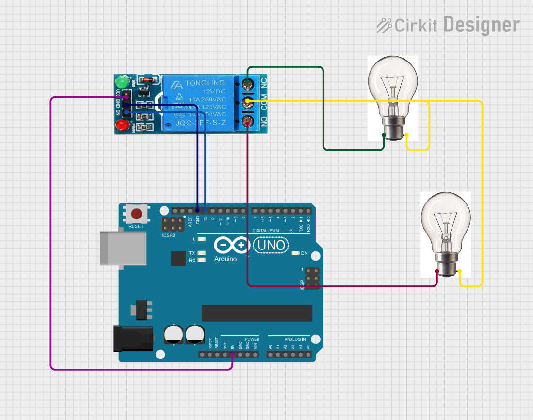
This circuit consists of an Arduino UNO microcontroller, a 12V single-channel relay, and two bulbs. The Arduino UNO is used to control the relay, which in turn switches the bulbs on and off. The relay is powered by the 5V output from the Arduino and is controlled by one of the Arduino's digital pins. The bulbs are connected to the relay such that one bulb is connected to the Normally Closed (NC) contact and the other to the Normally Open (NO) contact. The bulbs share a common ground connection through the relay's Common (COM) contact.
Component List
Arduino UNO
- Description: A microcontroller board based on the ATmega328P.
- Pins: UNUSED, IOREF, Reset, 3.3V, 5V, GND, Vin, A0-A5, SCL, SDA, AREF, D13-D0.
- Purpose: Acts as the control unit for the circuit, providing logic signals to the relay.
12V Single Channel Relay
- Description: An electromechanical switch that allows a low-power signal to control a higher power circuit.
- Pins: NC, COM, NO, IN, GND, VCC.
- Purpose: Switches the bulbs on and off based on the control signal from the Arduino UNO.
Bulb 1
- Description: An electric light with two terminals, +VE and _VE.
- Purpose: To illuminate when the relay is in the NC state or when the relay is not energized.
Bulb 2
- Description: An electric light with two terminals, +VE and _VE.
- Purpose: To illuminate when the relay is in the NO state or when the relay is energized.
Wiring Details
Arduino UNO
- 5V connected to Relay VCC.
- GND connected to Relay GND.
- D13 connected to Relay IN.
12V Single Channel Relay
- VCC connected to Arduino UNO 5V.
- GND connected to Arduino UNO GND.
- IN connected to Arduino UNO D13.
- NC connected to Bulb 1 +VE.
- COM connected to Bulb 1 _VE and Bulb 2 _VE.
- NO connected to Bulb 2 +VE.
Bulb 1
- +VE connected to Relay NC.
- _VE connected to Relay COM.
Bulb 2
- +VE connected to Relay NO.
- _VE connected to Relay COM.
Documented Code
Arduino UNO Code (sketch.ino)
void setup() {
  // Initialize serial communication at 9600 bits per second:
  Serial.begin(9600);

  // Set digital pin 13 as an OUTPUT:
  pinMode(13, OUTPUT);
}

void loop() {
  // Turn the relay on (connects NO to COM and disconnects NC from COM):
  digitalWrite(13, HIGH);
  delay(1000); // Wait for 1 second

  // Turn the relay off (connects NC to COM and disconnects NO from COM):
  digitalWrite(13, LOW);
  delay(1000); // Wait for 1 second
}
This code sets up the Arduino to communicate over the serial port at 9600 baud and configures pin 13 as an output. In the loop, it toggles pin 13 high and low, which turns the relay on and off, respectively, with a 1-second delay between each state change. This action causes the bulbs to alternate between being on and off.