
ESP32 and SD Card Module Data Logger with Wi-Fi Connectivity
View and Edit Project In Cirkit Designer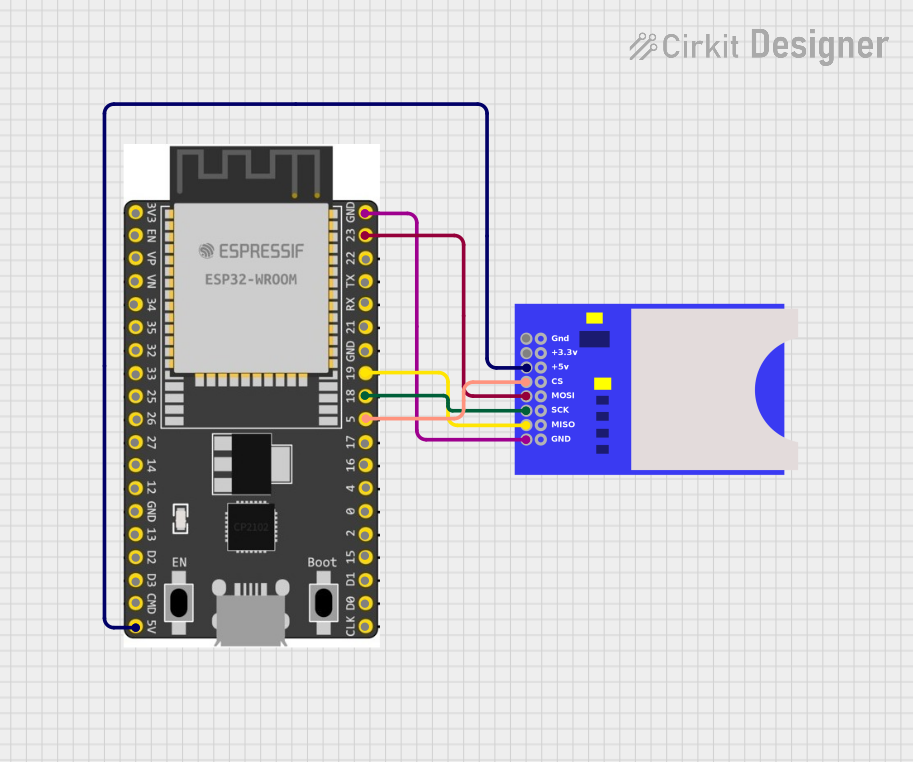
Circuit Documentation
Summary
This document provides a detailed overview of a circuit that integrates an ESP32 Wroom Dev Kit with an SD card module. The ESP32 serves as the main microcontroller, while the SD card module is used for data storage. The document includes a list of components, wiring details, and any associated code.
Component List
ESP32 Wroom Dev Kit
- Description: A powerful microcontroller with integrated Wi-Fi and Bluetooth capabilities.
- Pins: 3V3, EN, VP, VN, GPIO 34, GPIO 35, GPIO 32, GPIO 33, GPIO 25, GPIO 26, GPIO 27, GPIO 14, GND, GPIO 13, SD2, SD3, CMD, V5, GPIO 23, GPIO 22, TXD, RXD, GPIO 21, GPIO 19, GPIO 18, GPIO 5, GPIO 17, GPIO 16, GPIO 4, GPIO 0, GPIO 2, GPIO 15, SD1, SD0, CLK
- Purpose in Circuit: Main microcontroller for processing and control.
SD Card Module
- Description: A module for interfacing with SD cards, used for data storage.
- Pins: GND, +3.3V, +5V, CS, MOSI, SCK, MISO
- Purpose in Circuit: Provides data storage capabilities.
Wiring Details
ESP32 Wroom Dev Kit
- V5 is connected to +5V of the SD Card Module.
- GND is connected to GND of the SD Card Module.
- GPIO 23 is connected to MOSI of the SD Card Module.
- GPIO 19 is connected to MISO of the SD Card Module.
- GPIO 18 is connected to SCK of the SD Card Module.
- GPIO 5 is connected to CS of the SD Card Module.
SD Card Module
- +5V is connected to V5 of the ESP32 Wroom Dev Kit.
- GND is connected to GND of the ESP32 Wroom Dev Kit.
- MOSI is connected to GPIO 23 of the ESP32 Wroom Dev Kit.
- MISO is connected to GPIO 19 of the ESP32 Wroom Dev Kit.
- SCK is connected to GPIO 18 of the ESP32 Wroom Dev Kit.
- CS is connected to GPIO 5 of the ESP32 Wroom Dev Kit.
Code
No code is provided for this circuit.
This document provides a comprehensive overview of the circuit, including the components used and their interconnections. This should serve as a useful reference for understanding and replicating the circuit.