Itsy Bitsy M0 Express Controlled Multi-Servo System
Circuit Documentation
Summary
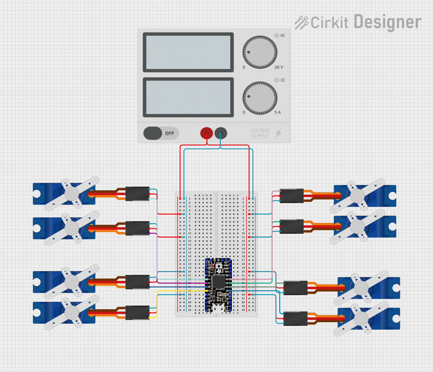
This circuit primarily consists of multiple Tower Pro SG90 servos controlled by an Itsy Bitsy M0 Express microcontroller. A power supply is included to provide the necessary voltage and current to the servos. The servos are connected to various digital and analog pins on the microcontroller for signal control, and they share a common power bus and ground connection from the power supply.
Component List
Microcontroller
- Itsy Bitsy M0 Express: A small, powerful, microcontroller board with a SAMD21G18 ARM Cortex M0 processor. It has a variety of digital and analog pins for interfacing with various components.
Servos
- Tower Pro SG90 Servo: A small and lightweight servo motor with a standard three-wire interface: signal, power (+5V), and ground (GND). These servos are used for precise angular movement.
Power Supply
- Power Supply: Provides a stable +5V and GND to power the servos.
Wiring Details
Itsy Bitsy M0 Express
- Signal Connections:
- Pin D7 to Servo 1 Signal
- Pin A4 to Servo 2 Signal
- Pin D9 to Servo 3 Signal
- Pin A3 to Servo 4 Signal
- Pin D10 to Servo 5 Signal
- Pin A2 to Servo 6 Signal
- Pin D11 to Servo 7 Signal
- Pin A1 to Servo 8 Signal
Tower Pro SG90 Servos
Servo 1:
- Signal: Connected to Itsy Bitsy M0 Express Pin D7
- +5V: Connected to Power Supply +
- GND: Connected to Power Supply -
Servo 2:
- Signal: Connected to Itsy Bitsy M0 Express Pin A4
- +5V: Connected to Power Supply +
- GND: Connected to Power Supply -
Servo 3:
- Signal: Connected to Itsy Bitsy M0 Express Pin D9
- +5V: Connected to Power Supply +
- GND: Connected to Power Supply -
Servo 4:
- Signal: Connected to Itsy Bitsy M0 Express Pin A3
- +5V: Connected to Power Supply +
- GND: Connected to Power Supply -
Servo 5:
- Signal: Connected to Itsy Bitsy M0 Express Pin D10
- +5V: Connected to Power Supply +
- GND: Connected to Power Supply -
Servo 6:
- Signal: Connected to Itsy Bitsy M0 Express Pin A2
- +5V: Connected to Power Supply +
- GND: Connected to Power Supply -
Servo 7:
- Signal: Connected to Itsy Bitsy M0 Express Pin D11
- +5V: Connected to Power Supply +
- GND: Connected to Power Supply -
Servo 8:
- Signal: Connected to Itsy Bitsy M0 Express Pin A1
- +5V: Connected to Power Supply +
- GND: Connected to Power Supply -
Power Supply
- +5V Output: Connected to the +5V pin of all Tower Pro SG90 servos.
- GND Output: Connected to the GND pin of all Tower Pro SG90 servos.
Documented Code
No code was provided for the Itsy Bitsy M0 Express microcontroller. The documentation of the code would typically include setup routines, control logic for the servos, and any communication protocols used. Since the code is not available, this section cannot be completed. If code becomes available, it should be documented here with explanations of its functionality and usage.