Arduino UNO Based Multi-Sensor Data Logger
Circuit Documentation
Summary
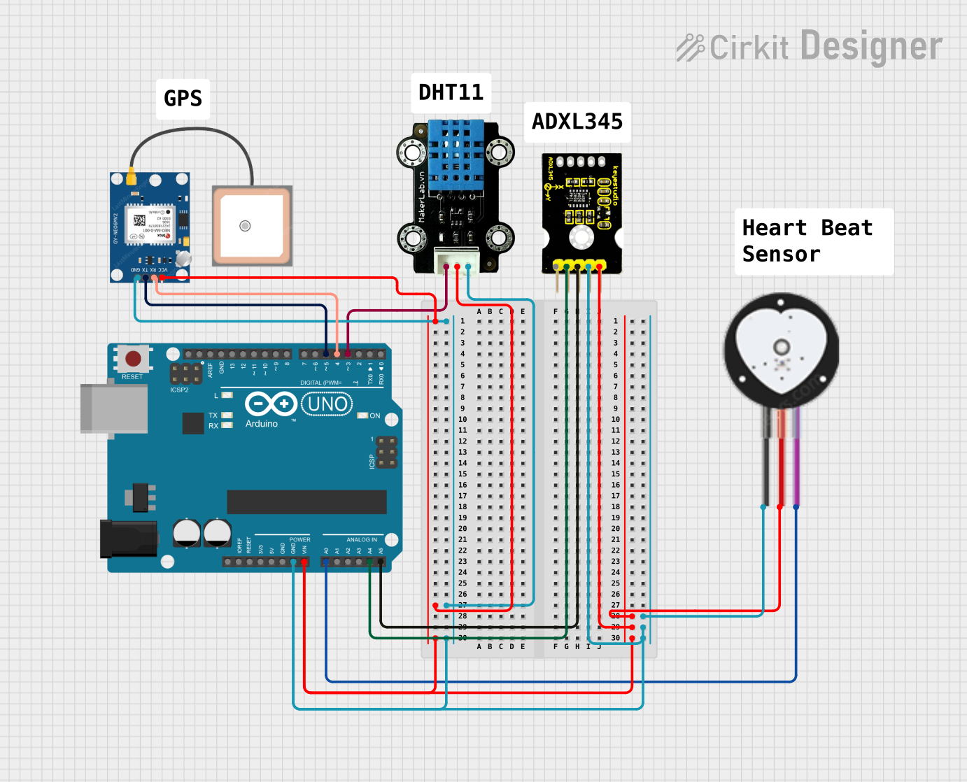
The circuit in question is designed around an Arduino UNO microcontroller and includes a variety of sensors and modules to perform multiple functions. The sensors include a Heart Pulse Sensor, a GPS NEO 6M module, an MKE-S14 DHT11 Temperature and Humidity Sensor, and an adxl345 keystudio accelerometer. The Arduino UNO is responsible for interfacing with these sensors, collecting data, and processing it as per the embedded code provided. The circuit is powered through the Arduino's Vin pin, with a common ground shared by all components.
Component List
Arduino UNO
- Description: A microcontroller board based on the ATmega328P.
- Purpose: Acts as the central processing unit of the circuit, reading sensor data and controlling the flow of the program.
Heart Pulse Sensor
- Description: A sensor that measures the heartbeat of a user.
- Purpose: To monitor and read the user's heart rate.
GPS NEO 6M
- Description: A GPS module that provides location data.
- Purpose: To provide real-time location tracking.
MKE-S14 DHT11 Temperature And Humidity Sensor
- Description: A sensor that measures ambient temperature and humidity.
- Purpose: To monitor environmental conditions.
adxl345 keystudio
- Description: A 3-axis accelerometer for sensing motion and orientation.
- Purpose: To measure acceleration and detect motion along three axes.
Wiring Details
Arduino UNO
- Vin: Connected to the VCC of GPS NEO 6M, Heart Pulse Sensor, adxl345 keystudio, and 5V of MKE-S14 DHT11.
- GND: Common ground shared with all sensors and modules.
- A0: Receives the SIGNAL from the Heart Pulse Sensor.
- A4 (SDA): Connected to the SDA pin of the adxl345 keystudio.
- A5 (SCL): Connected to the SCL pin of the adxl345 keystudio.
- D3: Connected to the SIG pin of the MKE-S14 DHT11.
- D4: Connected to the RX pin of the GPS NEO 6M.
- D5: Connected to the TX pin of the GPS NEO 6M.
Heart Pulse Sensor
- SIGNAL: Connected to A0 on the Arduino UNO.
- VCC: Connected to Vin on the Arduino UNO.
- GND: Connected to the common ground.
GPS NEO 6M
- VCC: Connected to Vin on the Arduino UNO.
- RX: Connected to D4 on the Arduino UNO.
- TX: Connected to D5 on the Arduino UNO.
- GND: Connected to the common ground.
MKE-S14 DHT11 Temperature And Humidity Sensor
- SIG: Connected to D3 on the Arduino UNO.
- 5V: Connected to Vin on the Arduino UNO.
- GND: Connected to the common ground.
adxl345 keystudio
- 5V: Connected to Vin on the Arduino UNO.
- SDA: Connected to A4 on the Arduino UNO.
- SCL: Connected to A5 on the Arduino UNO.
- GND: Connected to the common ground.
Documented Code
#include <Wire.h>
#include <Adafruit_Sensor.h>
#include <Adafruit_ADXL345_U.h>
#include <DHT.h>
#include <SoftwareSerial.h>

// Pin definitions
#define HEARTBEAT_PIN A0
#define DHT_PIN 3
#define GPS_RX_PIN 4
#define GPS_TX_PIN 5

// DHT11 setup
#define DHTTYPE DHT11
DHT dht(DHT_PIN, DHTTYPE);

// ADXL345 setup
Adafruit_ADXL345_Unified accel = Adafruit_ADXL345_Unified(12345);

// GPS setup
SoftwareSerial gpsSerial(GPS_RX_PIN, GPS_TX_PIN);

void setup() {
  Serial.begin(9600);
  gpsSerial.begin(9600);
  dht.begin();
  if (!accel.begin()) {
    Serial.println("No ADXL345 detected!");
    while (1);
  }
  Serial.println("Setup complete.");
}

void loop() {
  // Read heartbeat sensor
  int heartbeat = analogRead(HEARTBEAT_PIN);
  Serial.print("Heartbeat: ");
  Serial.println(heartbeat);

  // Read DHT11 sensor
  float h = dht.readHumidity();
  float t = dht.readTemperature();
  Serial.print("Humidity: ");
  Serial.print(h);
  Serial.print(" %\t");
  Serial.print("Temperature: ");
  Serial.print(t);
  Serial.println(" *C");

  // Read ADXL345 sensor
  sensors_event_t event;
  accel.getEvent(&event);
  Serial.print("X: ");
  Serial.print(event.acceleration.x);
  Serial.print(" \tY: ");
  Serial.print(event.acceleration.y);
  Serial.print(" \tZ: ");
  Serial.print(event.acceleration.z);
  Serial.println(" m/s^2");

  // Read GPS data
  while (gpsSerial.available()) {
    char c = gpsSerial.read();
    Serial.print(c);
  }

  delay(2000); // Delay for 2 seconds
}
Filename: sketch.ino
This code initializes and reads data from the connected sensors, then outputs the readings to the serial monitor. It includes setup and loop functions that are standard in Arduino programming. The setup function initializes serial communication and the sensors, while the loop function continuously reads data from the sensors and prints it to the serial monitor.