IR Sensor-Activated Water Pump with Relay and Darlington Transistor
Circuit Documentation
Summary of the Circuit
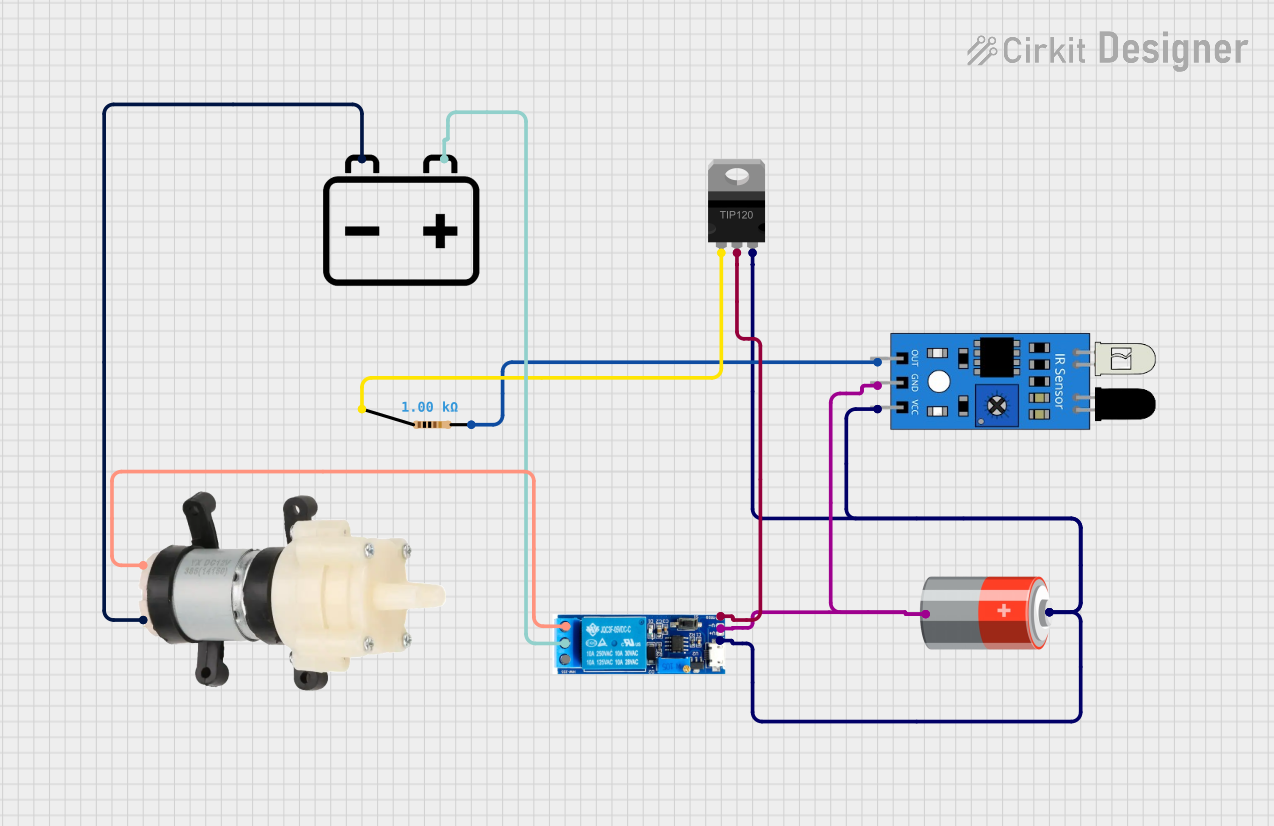
This circuit appears to be designed to control a Mini Diaphragm Water Pump using an IR sensor as a trigger. When the IR sensor detects an object, it sends a signal through a resistor to the base of a TIP120 Darlington Transistor. The transistor then activates a Relay module, which switches on the water pump. The circuit is powered by two separate power sources: a 5V battery for the IR sensor and relay module, and a 12V battery for the water pump.
Component List
IR Sensor
- Pins: out, gnd, vcc
- Description: An infrared sensor used to detect objects in its proximity.
5V Battery
- Pins: +, -
- Description: Provides power to the IR sensor and relay module.
Mini Diaphragm Water Pump
- Pins: Positive (+), Negative (-)
- Description: A pump that is actuated by the relay to move water upon receiving a signal.
Resistor
- Pins: pin1, pin2
- Description: Limits current to the base of the TIP120 transistor.
- Properties: 1000 Ohms resistance.
TIP120 Hi-Current Darlington Transistor
- Pins: BASE, COLLECTOR, EMITTER
- Description: Amplifies the signal from the IR sensor to switch the relay module.
12V Battery
- Pins: +, -
- Description: Provides power to the Mini Diaphragm Water Pump.
Relay Module 5V-30V
- Pins: common contact, normally open, normally closed, trigger, V-, V+
- Description: Electrically operated switch that controls the water pump.
Wiring Details
IR Sensor
- out: Connected to one end of the Resistor.
- gnd: Connected to the negative terminal of the 5V Battery.
- vcc: Connected to the positive terminal of the 5V Battery and the EMITTER of the TIP120 Transistor.
5V Battery
- + (positive): Connected to the V+ of the Relay module and the vcc of the IR Sensor.
- - (negative): Connected to the V- of the Relay module and the gnd of the IR Sensor.
Mini Diaphragm Water Pump
- Positive (+): Connected to the normally open contact of the Relay module.
- Negative (-): Connected to the negative terminal of the 12V Battery.
Resistor
- pin1: Connected to the BASE of the TIP120 Transistor.
- pin2: Connected to the out of the IR Sensor.
TIP120 Hi-Current Darlington Transistor
- BASE: Connected to one end of the Resistor.
- COLLECTOR: Connected to the trigger of the Relay module.
- EMITTER: Connected to the vcc of the IR Sensor.
12V Battery
- + (positive): Connected to the common contact of the Relay module.
- - (negative): Connected to the Negative (-) of the Mini Diaphragm Water Pump.
Relay Module 5V-30V
- common contact: Connected to the positive terminal of the 12V Battery.
- normally open: Connected to the Positive (+) of the Mini Diaphragm Water Pump.
- normally closed: Not connected in this circuit.
- trigger: Connected to the COLLECTOR of the TIP120 Transistor.
- V-: Connected to the negative terminal of the 5V Battery.
- V+: Connected to the positive terminal of the 5V Battery.
Documented Code
There is no embedded code provided for any microcontrollers in this circuit. If the circuit is intended to be controlled by a microcontroller, the code would be necessary to define the behavior of the IR sensor and the subsequent activation of the relay and water pump. Without the code, the circuit is assumed to operate directly through the hardware components as described above.