
Circuit Documentation
Summary of the Circuit
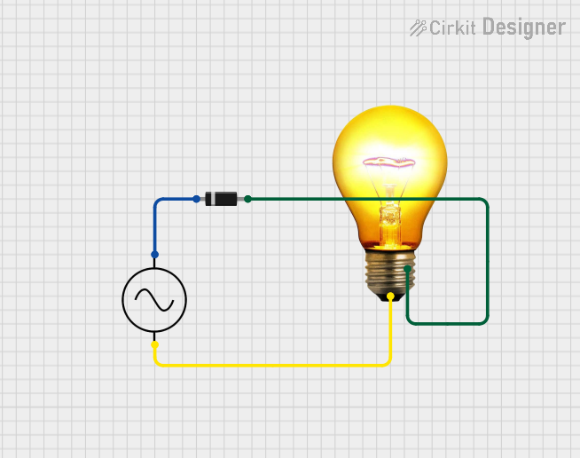
The circuit described by the provided inputs is a simple AC circuit that includes an AC power supply, a diode, and an AC bulb. The diode is connected in series with the AC bulb, and the combination is powered by the AC supply. The purpose of the diode in this circuit is likely to allow current to flow in one direction, effectively converting the AC supply into a half-wave rectified signal for the bulb. This could be used to reduce the power consumption of the bulb or to protect the circuit from reverse voltage.
Component List
Diode
- Description: A semiconductor device that allows current to flow in one direction only.
- Pins:
- Cathode: The negative side of the diode.
- Anode: The positive side of the diode.
AC Supply
- Description: A source of alternating current (AC) electrical power.
- Pins:
- +ve: Positive voltage supply.
- -ve: Negative voltage supply or ground.
AC Bulb
- Description: An electric bulb designed to operate with alternating current (AC).
- Pins:
- P: One terminal of the bulb.
- N: The other terminal of the bulb.
Wiring Details
Diode
- Cathode is connected to the +ve pin of the AC Supply.
- Anode is connected to the N pin of the AC Bulb.
AC Supply
- +ve pin is connected to the Cathode of the Diode.
- -ve pin is connected to the P pin of the AC Bulb.
AC Bulb
- P pin is connected to the -ve pin of the AC Supply.
- N pin is connected to the Anode of the Diode.
Documented Code
There is no microcontroller or embedded code associated with this circuit as per the provided inputs. Therefore, this section is not applicable to the current documentation.
This documentation provides an overview of the circuit's components and their connections. It is essential to note that the actual implementation of the circuit should be done by a qualified individual, adhering to all relevant safety standards and regulations.