Arduino-Controlled Water Management System with Ultrasonic Sensing and Solenoid Valves
Circuit Documentation
Summary
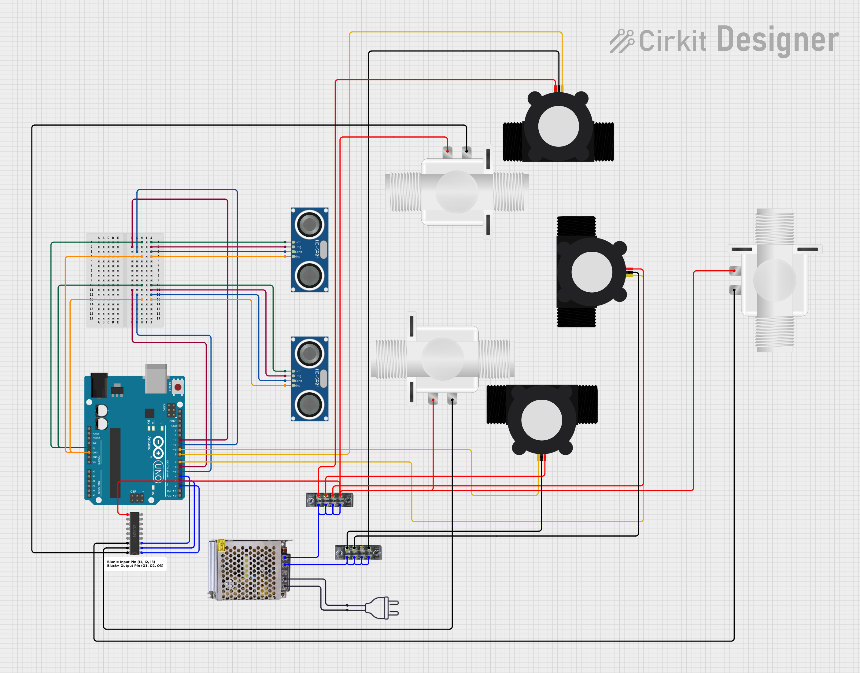
The circuit in question is designed to control a system of solenoid valves based on the readings from ultrasonic sensors and water flow meters. The Arduino UNO serves as the central microcontroller, interfacing with two HC-SR04 Ultrasonic Sensors, three YF-S201 Water Flow Meters, and three Plastic Solenoid Valves through a ULN2803 Darlington Array. The ULN2803 is used to drive the solenoid valves, which require more current than the Arduino can provide directly. The power supply is a 12V 5A unit, which is connected to the system through a terminal block. The circuit is designed to detect the presence of an object within a certain range and control the flow of water through the solenoid valves accordingly.
Component List
- Plastic Solenoid Valve: An electrically controlled valve used for controlling the flow of a liquid.
- ULN2803 Darlington Array: An integrated circuit that contains multiple Darlington transistor pairs for driving high-current loads.
- Arduino UNO: A microcontroller board based on the ATmega328P, with digital input/output pins, analog inputs, and various other features.
- HC-SR04 Ultrasonic Sensor: A sensor that measures distance by emitting ultrasonic waves and measuring the time taken for the echo to return.
- YF-S201 Water Flow Meter: A device that measures the flow rate of water passing through it.
- POWER SUPPLY 12V 5AMP: A power supply unit that converts 220V AC to 12V DC, providing power to the circuit.
- Terminal Block (terminalblock-04-01): A type of electrical connector where multiple individual circuits are connected to the same physical block.
- Power 220V: Represents the main AC power connection to the circuit.
Wiring Details
Plastic Solenoid Valve
- Valve 1: Controlled by ULN2803 Darlington Array output O1.
- Valve 2: Controlled by ULN2803 Darlington Array output O2.
- Valve 3: Controlled by ULN2803 Darlington Array output O3.
- Common: All valves share a common connection to the Darlington Array COMMON pin.
ULN2803 Darlington Array
- Inputs (I1, I2, I3): Connected to Arduino digital pins D2, D3, and D4 respectively.
- Outputs (O1, O2, O3): Connected to the control pins of the solenoid valves.
- COMMON: Connected to the positive side of the solenoid valves.
- GND: Connected to the ground of the circuit.
Arduino UNO
- Digital Pins (D2, D3, D4): Control signals for the ULN2803 Darlington Array.
- Digital Pins (D5, D6, D10, D11): Connected to the ECHO and TRIG pins of the HC-SR04 Ultrasonic Sensors.
- Digital Pins (D7, D8, D9): Connected to the SIG pins of the YF-S201 Water Flow Meters.
HC-SR04 Ultrasonic Sensor
- Sensor 1: TRIG connected to Arduino D11, ECHO connected to Arduino D10.
- Sensor 2: TRIG connected to Arduino D6, ECHO connected to Arduino D5.
- VCC: Connected to Arduino 5V.
- GND: Connected to Arduino GND.
YF-S201 Water Flow Meter
- Meter 1: SIG connected to Arduino D9.
- Meter 2: SIG connected to Arduino D8.
- Meter 3: SIG connected to Arduino D7.
- VCC: Connected to the power supply through the terminal block.
- GND: Connected to the ground through the terminal block.
POWER SUPPLY 12V 5AMP
- 220V AC Input: Connected to the power 220V AC source.
- 12V-24V DC Output: Connected to the terminal block to supply power to the solenoid valves and water flow meters.
Terminal Block
- Terminal Block 1: Used for connecting the GND and VCC of the water flow meters.
- Terminal Block 2: Used for connecting the solenoid valves to the power supply.
Documented Code
// Arduino UNO Code
#define TRIG_PIN1 11
#define ECHO_PIN1 10
#define TRIG_PIN2 6
#define ECHO_PIN2 5
#define WATER_FLOW_SENSOR_PIN1 9
#define WATER_FLOW_SENSOR_PIN2 8
#define WATER_FLOW_SENSOR_PIN3 7
#define SolenoidValvePin1 2
#define SolenoidValvePin2 3
#define SolenoidValvePin3 4

const float soundSpeed = 343.0; // Speed of sound in m/s
const float maxDistance = 5.00; // Maximum distance you want to check for objects (in meters)

bool isObjectDetected(int trigPin, int echoPin) {
  digitalWrite(trigPin, LOW);
  delayMicroseconds(2);
  digitalWrite(trigPin, HIGH);
  delayMicroseconds(10);
  digitalWrite(trigPin, LOW);

  unsigned long timeout = 30000; // 30 milliseconds timeout for maxDistance
  float duration = pulseIn(echoPin, HIGH, timeout);
  if (duration == 0) {
    return false; // Timeout occurred, no object detected
  }

  float distance = (duration * soundSpeed) / (2 * 1000); // Convert to meters

  return (distance <= maxDistance); // Return true if object detected within the specified range
}

void setup() {
  Serial.begin(9600);
  pinMode(ECHO_PIN1, INPUT);
  pinMode(TRIG_PIN1, OUTPUT);
  pinMode(TRIG_PIN2, OUTPUT);
  pinMode(ECHO_PIN2, INPUT);
  pinMode(WATER_FLOW_SENSOR_PIN1, INPUT);
  pinMode(WATER_FLOW_SENSOR_PIN2, INPUT);
  pinMode(WATER_FLOW_SENSOR_PIN3, INPUT);
  pinMode(SolenoidValvePin1, OUTPUT);
  pinMode(SolenoidValvePin2, OUTPUT);
  pinMode(SolenoidValvePin3, OUTPUT);

  // Initialize solenoid valves to off
  digitalWrite(SolenoidValvePin1, LOW);
  digitalWrite(SolenoidValvePin2, LOW);
  digitalWrite(SolenoidValvePin3, LOW);
}

void loop() {
  // The loop contains logic to read the ultrasonic sensors and water flow meters
  // and control the solenoid valves accordingly.
  // Please refer to the full code for the complete logic.
}
Note: The provided code is a snippet and does not represent the complete logic. The full code includes additional logic for reading the water flow sensors and controlling the solenoid valves based on the sensor readings. The code also contains a manual reset function to turn off the solenoid valves.