
Arduino UNO R4 WiFi Controlled Temperature and Humidity Sensor with LED Indicator
View and Edit Project In Cirkit Designer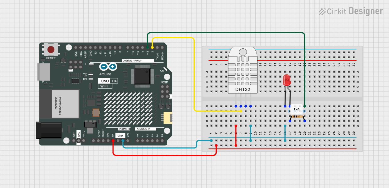
Circuit Documentation
Summary of the Circuit
This circuit is designed to interface a DHT22 temperature and humidity sensor with an Arduino UNO R4 WiFi microcontroller. The DHT22 sensor is powered by the 5V supply from the Arduino and communicates via a digital pin. Additionally, there is an LED with a series resistor that is controlled by another digital pin on the Arduino. The LED serves as an indicator and the resistor limits the current through the LED to safe levels.
Component List
DHT22 (Wokwi Compatible)
- Description: A digital temperature and humidity sensor.
- Pins: VCC, SDA, NC, GND
Resistor
- Description: A passive two-terminal electrical component that implements electrical resistance as a circuit element.
- Value: 1000 Ohms
LED: Two Pin (red)
- Description: A red light-emitting diode.
- Pins: cathode, anode
Arduino UNO R4 WiFi
- Description: A microcontroller board based on the ATmega328P with WiFi capabilities.
- Pins: OFF, GND, VRTC, IIC0_SCL, IIC0_SDA, 3V3, GPIO 41, GPIO 0, GPIO 42, GPIO 43, GPIO 44, BOOT, IOREF, RESET, 5V, VIN, A0, A1, A2, A3, A4, A5, RSPCKA, CIPO, COPI, D0/RX, D1/TX, D2, D3, D4, D5, D6, D7, D8, D9, D10, D11, D12, D13, AREF, SDA, SCL
Wiring Details
DHT22 (Wokwi Compatible)
- VCC connected to Arduino UNO R4 WiFi 5V
- SDA connected to Arduino UNO R4 WiFi D2
- GND connected to Arduino UNO R4 WiFi GND
Resistor
- pin1 connected to LED (red) anode
- pin2 connected to Arduino UNO R4 WiFi D3
LED: Two Pin (red)
- cathode connected to Arduino UNO R4 WiFi GND
- anode connected to Resistor pin1
Arduino UNO R4 WiFi
- 5V connected to DHT22 VCC
- D2 connected to DHT22 SDA
- GND connected to DHT22 GND and LED cathode
- D3 connected to Resistor pin2
Documented Code
sketch.ino
void setup() {
  // put your setup code here, to run once:

}

void loop() {
  // put your main code here, to run repeatedly:

}
documentation.txt
(No additional documentation provided)