
Arduino Nano-Based Tractor Brake and Clutch Control System with BTS7960 Motor Drivers
View and Edit Project In Cirkit Designer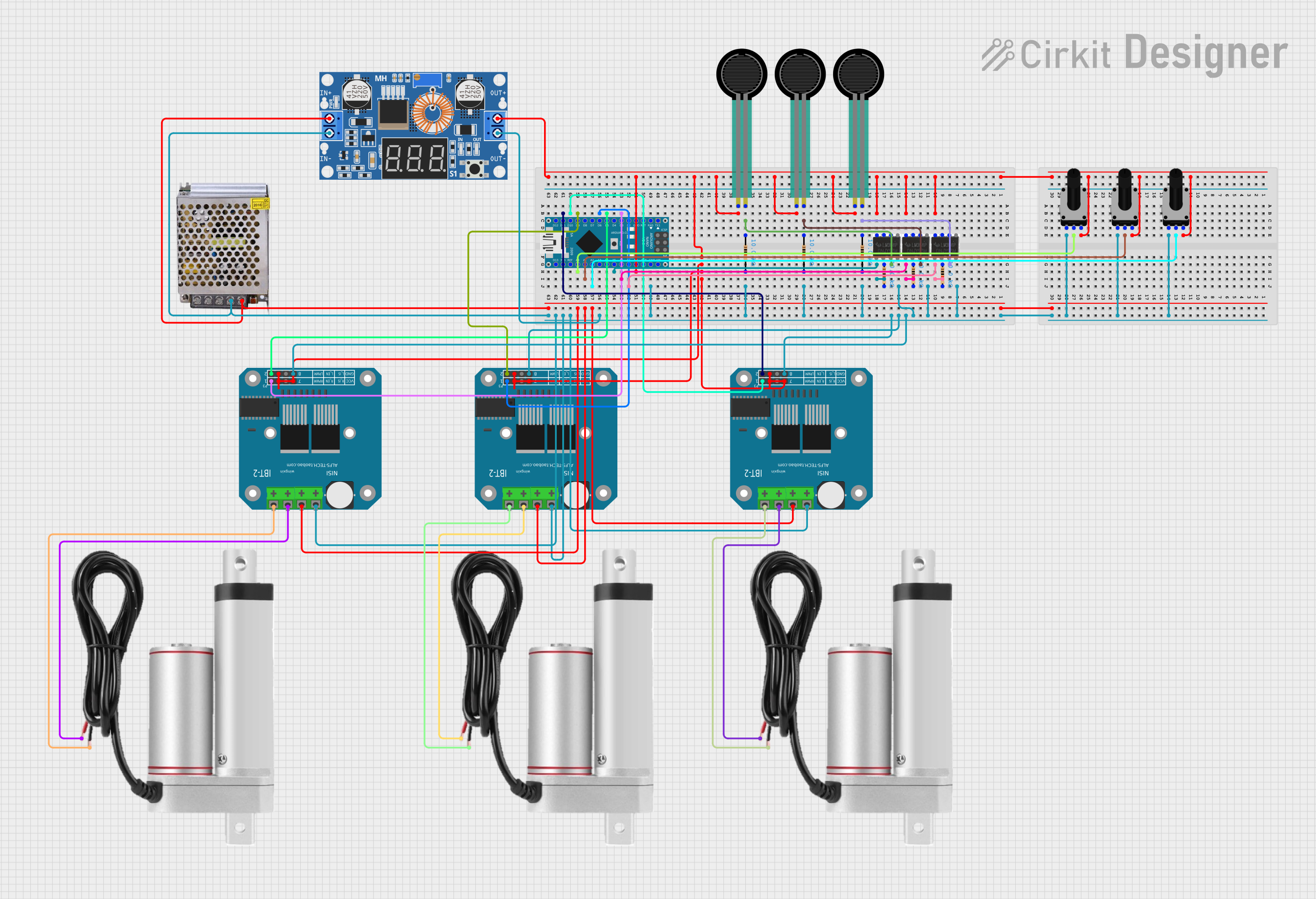
Circuit Documentation
Summary
This circuit is designed to control the brake and clutch of a tractor using linear actuators. The system reads values from force-sensing resistors (FSRs) and rotary potentiometers to control the actuators via BTS7960 motor drivers. When the FSR values exceed a predefined threshold, the actuators are activated to reduce the force needed to push the pedals.
Component List
LMA
- Pins: +, -
- Description: Linear Motor Actuator
- Purpose: Actuates the brake and clutch pedals.
POWER SUPPLY 12V 5AMP
- Pins: 220V Positive Pole (AC), 220V Negative Pole (AC), GND, GND (DC), 12V-24V Output (DC)
- Description: Power supply unit
- Purpose: Provides power to the circuit.
BTS7960 Motor Driver
- Pins: Pin 1, Pin 2, Pin 3, Pin 4, Pin 5, Pin 6, Pin 7, Pin 8, Pin 9, Pin 10, Pin 11, Pin 12
- Description: Motor driver
- Purpose: Controls the linear actuators.
Rotary Potentiometer
- Pins: leg1, wiper, leg2
- Description: Variable resistor
- Purpose: Reads the position of the brake and clutch pedals.
- Properties: Resistance: 10000 Ohms
XL4015 5A DC Buck Step-down
- Pins: Output +, Output -, Input +, Input -
- Description: DC-DC converter
- Purpose: Steps down the voltage from the power supply.
LM358 Op-Amp
- Pins: 8, 1, 2, 3, 4, 5, 6, 7
- Description: Operational amplifier
- Purpose: Amplifies the signals from the FSRs.
Arduino Nano
- Pins: D1/TX, D0/RX, RESET, GND, D2, D3, D4, D5, D6, D7, D8, D9, D10, D11/MOSI, D12/MISO, VIN, 5V, A7, A6, A5, A4, A3, A2, A1, A0, AREF, 3V3, D13/SCK
- Description: Microcontroller
- Purpose: Reads sensor values and controls the motor drivers.
Force Sensing Resistor
- Pins: pin 0, pin 1
- Description: Force sensor
- Purpose: Measures the force applied to the brake and clutch pedals.
Resistor
- Pins: pin1, pin2
- Description: Fixed resistor
- Purpose: Used in voltage divider circuits.
- Properties: Resistance: 10000 Ohms
Wiring Details
LMA
- Pin + connected to BTS7960 Motor Driver Pin 10
- Pin - connected to BTS7960 Motor Driver Pin 9
POWER SUPPLY 12V 5AMP
GND (DC) connected to:
- XL4015 5A DC Buck Step-down Input -
- XL4015 5A DC Buck Step-down Output -
- Arduino Nano GND
- BTS7960 Motor Driver Pin 1
- BTS7960 Motor Driver Pin 12
- Rotary Potentiometer leg1
12V-24V Output (DC) connected to XL4015 5A DC Buck Step-down Input +
BTS7960 Motor Driver
- Pin 1 connected to GND
- Pin 3 connected to LM358 Op-Amp Pin 8
- Pin 4 connected to:
- Arduino Nano D5
- Arduino Nano D9
- Arduino Nano D11/MOSI
- Pin 5 connected to LM358 Op-Amp Pin 8
- Pin 7 connected to LM358 Op-Amp Pin 8
- Pin 8 connected to:
- Arduino Nano D3
- Arduino Nano D6
- Arduino Nano D10
- Pin 9 connected to LMA Pin -
- Pin 10 connected to LMA Pin +
- Pin 11 connected to LM358 Op-Amp Pin 8
- Pin 12 connected to GND
Rotary Potentiometer
- leg1 connected to GND
- leg2 connected to 5V
- wiper connected to:
- Arduino Nano A0
- Arduino Nano A1
- Arduino Nano A2
XL4015 5A DC Buck Step-down
- Input + connected to POWER SUPPLY 12V 5AMP 12V-24V Output (DC)
- Input - connected to GND
- Output + connected to Arduino Nano 5V
- Output - connected to GND
LM358 Op-Amp
- Pin 8 connected to:
- BTS7960 Motor Driver Pin 3
- BTS7960 Motor Driver Pin 5
- BTS7960 Motor Driver Pin 7
- BTS7960 Motor Driver Pin 11
Arduino Nano
- GND connected to GND
- 5V connected to XL4015 5A DC Buck Step-down Output +
- A0 connected to Rotary Potentiometer wiper
- A1 connected to Rotary Potentiometer wiper
- A2 connected to Rotary Potentiometer wiper
- A5 connected to Force Sensing Resistor pin 0
- A6 connected to Force Sensing Resistor pin 1
- A7 connected to Force Sensing Resistor pin 1
- D3 connected to BTS7960 Motor Driver Pin 8
- D5 connected to BTS7960 Motor Driver Pin 4
- D6 connected to BTS7960 Motor Driver Pin 8
- D9 connected to BTS7960 Motor Driver Pin 4
- D10 connected to BTS7960 Motor Driver Pin 8
- D11/MOSI connected to BTS7960 Motor Driver Pin 4
Force Sensing Resistor
- pin 0 connected to LM358 Op-Amp Pin 8
- pin 1 connected to:
- Resistor pin1
- Arduino Nano A6
- Arduino Nano A7
Resistor
- pin1 connected to:
- Force Sensing Resistor pin 1
- Arduino Nano A6
- Arduino Nano A7
- pin2 connected to:
- GND
- Arduino Nano A5
Code Documentation
/*
 * Tractor Brake and Clutch Control
 * This code reads values from FSRs and potentiometers to control linear actuators
 * via BTS7960 motor drivers. When FSR values exceed a threshold, the actuators
 * are activated to reduce the force needed to push the pedals.
 */

// Pin definitions
const int fsrBrake1Pin = A6;
const int fsrBrake2Pin = A7;
const int fsrClutchPin = A5;
const int potBrake1Pin = A0;
const int potBrake2Pin = A1;
const int potClutchPin = A2;

const int brake1ControlPin1 = 3;
const int brake1ControlPin2 = 5;
const int brake2ControlPin1 = 6;
const int brake2ControlPin2 = 9;
const int clutchControlPin1 = 10;
const int clutchControlPin2 = 11;

const int threshold = 500; // FSR threshold

void setup() {
  // Initialize serial communication
  Serial.begin(9600);

  // Set control pins as outputs
  pinMode(brake1ControlPin1, OUTPUT);
  pinMode(brake1ControlPin2, OUTPUT);
  pinMode(brake2ControlPin1, OUTPUT);
  pinMode(brake2ControlPin2, OUTPUT);
  pinMode(clutchControlPin1, OUTPUT);
  pinMode(clutchControlPin2, OUTPUT);
}

void loop() {
  // Read FSR values
  int fsrBrake1Value = analogRead(fsrBrake1Pin);
  int fsrBrake2Value = analogRead(fsrBrake2Pin);
  int fsrClutchValue = analogRead(fsrClutchPin);

  // Read potentiometer values
  int potBrake1Value = analogRead(potBrake1Pin);
  int potBrake