
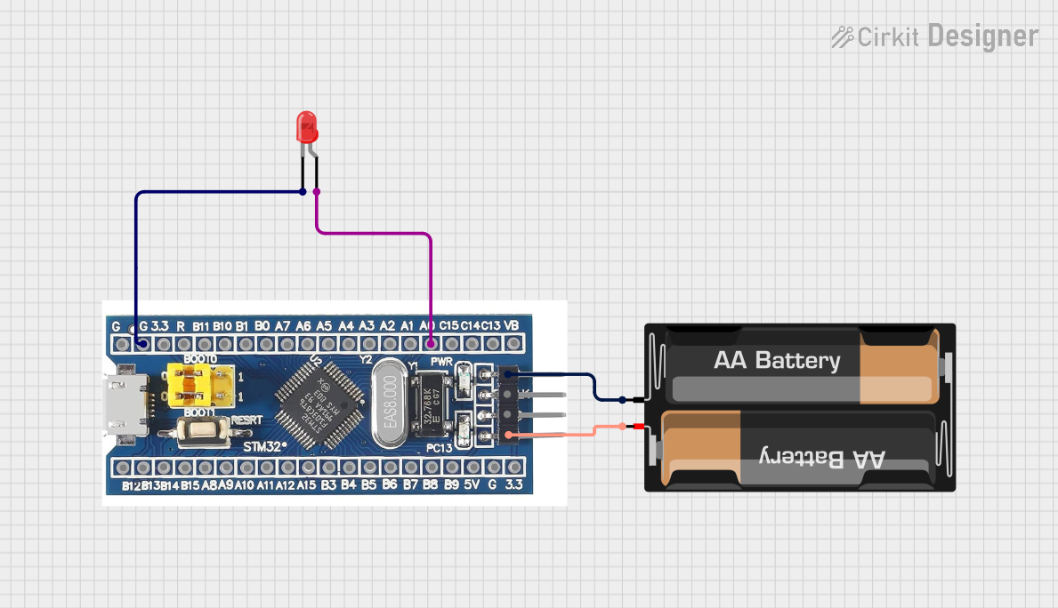
Circuit Documentation
Summary
This circuit consists of an STM32F103C8T6 microcontroller, a red LED, and a 2 x AA battery mount. The microcontroller controls the LED, turning it on and off with a 1-second interval. The circuit is powered by the 2 x AA battery mount.
Component List
STM32F103C8T6
- Description: A 32-bit ARM Cortex-M3 microcontroller.
- Pins: GND, 3.3V, reset, B11, B10, B1, B0, A7, A6, A5, A4, A3, A2, A1, A0, C15, C14, C13, VBT, 3.3, 5V, B12, B13, b14, B15, A8, A9, A10, A11, A12, A15, B3, B4, B5, B6, B7, B8, B9, SWIO, SWCLK
LED: Two Pin (red)
- Description: A standard red LED.
- Pins: cathode, anode
2 x AA Battery Mount
- Description: A battery holder for two AA batteries.
- Pins: -, +
Wiring Details
STM32F103C8T6
- GND is connected to:
- LED: Two Pin (red) cathode
- 2 x AA Battery Mount -
- A0 is connected to LED: Two Pin (red) anode
- 3.3V is connected to 2 x AA Battery Mount +
LED: Two Pin (red)
- cathode is connected to STM32F103C8T6 GND
- anode is connected to STM32F103C8T6 A0
2 x AA Battery Mount
- - is connected to STM32F103C8T6 GND
- + is connected to STM32F103C8T6 3.3V
Code Documentation
Main Code
#include "stm32f1xx_hal.h"

void SystemClock_Config(void);
static void MX_GPIO_Init(void);

int main(void)
{
    // Initialize the HAL Library
    HAL_Init();

    // Configure the system clock
    SystemClock_Config();

    // Initialize all configured peripherals (GPIO)
    MX_GPIO_Init();

    // Main loop
    while (1)
    {
        // Turn on the LED
        HAL_GPIO_WritePin(GPIOA, GPIO_PIN_0, GPIO_PIN_SET);

        // Add a delay to keep the LED on
        HAL_Delay(1000); // 1 second delay

        // Turn off the LED
        HAL_GPIO_WritePin(GPIOA, GPIO_PIN_0, GPIO_PIN_RESET);

        // Add a delay to keep the LED off
        HAL_Delay(1000); // 1 second delay
    }
}

void SystemClock_Config(void)
{
    // System Clock Configuration code here
    // This is usually auto-generated by STM32CubeMX
}

static void MX_GPIO_Init(void)
{
    GPIO_InitTypeDef GPIO_InitStruct = {0};

    // GPIO Ports Clock Enable
    __HAL_RCC_GPIOA_CLK_ENABLE();

    // Configure GPIO pin Output Level
    HAL_GPIO_WritePin(GPIOA, GPIO_PIN_0, GPIO_PIN_RESET);

    // Configure GPIO pin : PA0
    GPIO_InitStruct.Pin = GPIO_PIN_0;
    GPIO_InitStruct.Mode = GPIO_MODE_OUTPUT_PP;
    GPIO_InitStruct.Pull = GPIO_NOPULL;
    GPIO_InitStruct.Speed = GPIO_SPEED_FREQ_LOW;
    HAL_GPIO_Init(GPIOA, &GPIO_InitStruct);
}
This code initializes the STM32F103C8T6 microcontroller, configures the system clock, and sets up GPIO pin A0 as an output. The main loop toggles the LED connected to pin A0 on and off with a 1-second delay.