
ESP32-Controlled Water Quality Monitoring System with Peristaltic Pump and TDS Sensor
View and Edit Project In Cirkit Designer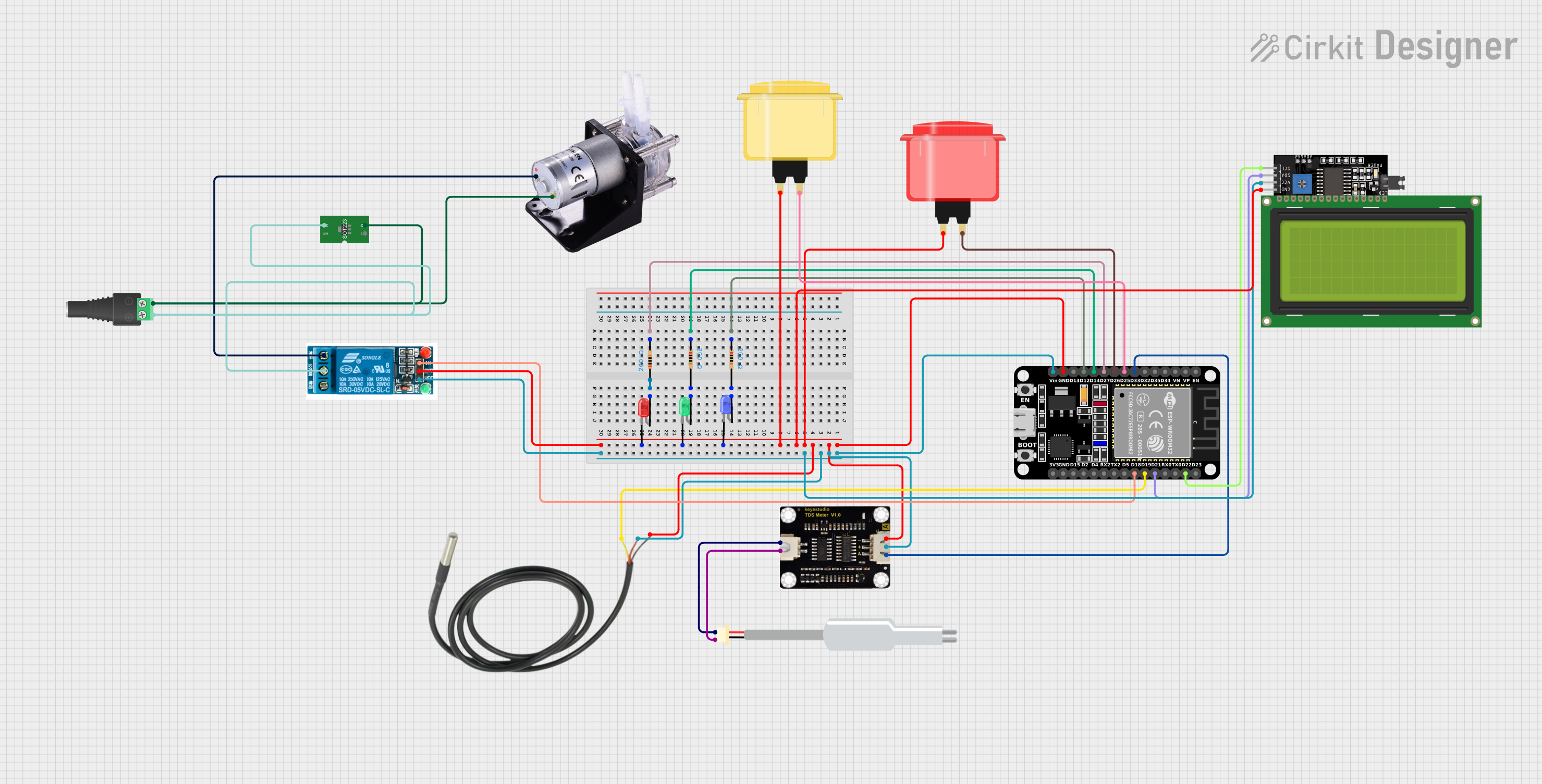
Circuit Documentation
Summary
This circuit is designed to control a peristaltic pump, read data from a TDS (Total Dissolved Solids) sensor, and display information on an LCD display. It also includes temperature sensing capabilities and user input through arcade buttons. The ESP32 microcontroller serves as the central processing unit, interfacing with the sensors, the display, and controlling the relay which in turn controls the peristaltic pump. The circuit includes voltage regulation and LED indicators for visual feedback.
Component List
Peristaltic Pump
- A pump that moves fluid by alternately contracting and relaxing.
- Pins:
+,-
ESP32 (30 pin)
- A microcontroller with Wi-Fi and Bluetooth capabilities.
- Pins:
EN,VP,VN,D34,D35,D32,D33,D25,D26,D27,D14,D12,D13,GND,Vin,D23,D22,TX0,RX0,D21,D19,D18,D5,TX2,RX2,D4,D2,D15,3V3
TDS Sensor
- A sensor used to measure the total dissolved solids in a liquid.
- Pins:
P1,P2,+,-,A
Sonda Sensor TDS
- A probe that works with the TDS sensor to measure water quality.
- Pins:
+,-
LCD Display 20x4 I2C
- An alphanumeric liquid crystal display with I2C communication.
- Pins:
SCL,SDA,VCC,GND
Temperature Sensor
- A sensor for measuring temperature.
- Pins:
Temp GND Black,Temp VDD Red,Temp DQ Data Yellow
2.1mm Barrel Jack with Terminal Block
- A power connector for supplying power to the circuit.
- Pins:
POS,NEG
5v Relay
- An electromechanical switch used to control high power devices.
- Pins:
Normally Open,Common terminal,Normally Closed,In,GND,VCC
Voltage Regulator
- A device that maintains a constant voltage level.
- Pins:
ADJ,OUT,IN
LED: Two Pin (green, blue, red)
- Light Emitting Diodes used as visual indicators.
- Pins:
cathode,anode
Resistor (200 Ohms)
- A passive two-terminal electrical component that implements electrical resistance.
- Pins:
pin1,pin2 - Resistance:
200 Ohms
Arcade Button (yellow, red)
- A push-button switch that provides user input to the system.
- Pins:
no name yet
Wiring Details
Peristaltic Pump
+connected to the Normally Open pin of the 5v relay.-connected to the NEG pin of the 2.1mm Barrel Jack and OUT pin of the Voltage Regulator.
ESP32 (30 pin)
D33connected to the A pin of the TDS Sensor.D25connected to the Arcade Button (yellow).D26connected to the Arcade Button (red).D27,D14,D12connected to the pin2 of the corresponding 200 Ohm Resistors.GNDconnected to the cathodes of the LEDs, GND pins of the TDS Sensor, LCD Display, Temperature Sensor, and the GND pin of the 5v relay.Vinconnected to the + pins of the TDS Sensor, VCC pins of the LCD Display, Temp VDD Red of the Temperature Sensor, and the VCC pin of the 5v relay.D22connected to the SCL pin of the LCD Display.D21connected to the SDA pin of the LCD Display.D19connected to the Temp DQ Data Yellow pin of the Temperature Sensor.D18connected to the In pin of the 5v relay.
TDS Sensor
P1connected to the + pin of the Sonda Sensor TDS.P2connected to the - pin of the Sonda Sensor TDS.+connected to the Vin pin of the ESP32.-connected to the GND pin of the ESP32.Aconnected to the D33 pin of the ESP32.
Sonda Sensor TDS
+connected to the P1 pin of the TDS Sensor.-connected to the P2 pin of the TDS Sensor.
LCD Display 20x4 I2C
SCLconnected to the D22 pin of the ESP32.SDAconnected to the D21 pin of the ESP32.VCCconnected to the Vin pin of the ESP32.GNDconnected to the GND pin of the ESP32.
Temperature Sensor
Temp GND Blackconnected to the GND pin of the ESP32.Temp VDD Redconnected to the Vin pin of the ESP32.Temp DQ Data Yellowconnected to the D19 pin of the ESP32.
2.1mm Barrel Jack with Terminal Block
POSconnected to the IN pin of the Voltage Regulator and the Common terminal pin of the 5v relay.NEGconnected to the - pin of the Peristaltic Pump.
5v Relay
Normally Openconnected to the + pin of the Peristaltic Pump.Common terminalconnected to the POS pin of the 2.1mm Barrel Jack.Inconnected to the D18 pin of the ESP32.GNDconnected to the GND pin of the ESP32.VCCconnected to the Vin pin of the ESP32.
Voltage Regulator
ADJ(not connected in the provided net list).OUTconnected to the - pin of the Peristaltic Pump.INconnected to the POS pin of the 2.1mm Barrel Jack.
LED: Two Pin (green, blue, red)
cathodeconnected to the GND pin of the ESP32.anodeof the green LED connected to the pin2 of the corresponding 200 Ohm Resistor.anodeof the blue LED connected to the pin2 of the corresponding 200 Ohm Resistor.anodeof the red LED connected to the pin1 of the corresponding 200 Ohm Resistor.
Resistor (200 Ohms)
pin1of one resistor connected to the D27 pin of the ESP32 and the anode of the green LED.pin2of the same resistor connected to the cathode of the green LED.pin1of another resistor connected to the D14 pin of the ESP32 and the anode of the blue LED.pin2of the same resistor connected to the cathode of the blue LED.pin1of the third resistor connected to the D12 pin of the ESP32 and the anode of the red LED.pin2of the same resistor connected to the cathode of the red LED.
Arcade Button (yellow, red)
- The pin of the yellow button connected to the D25 pin of the ESP32.
- The pin of the red button connected to the D26 pin of the ESP32.
Documented Code
No code was provided for the microcontroller(s) in the circuit. The documentation of the code would typically include descriptions of the functions, the main loop, and any interrupt service routines, along with explanations of how the code interacts with the hardware components listed above.