
Circuit Documentation
Summary of the Circuit
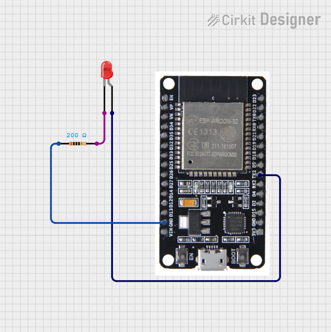
This circuit appears to be designed to control an LED using an ESP32 microcontroller. The ESP32 is a versatile microcontroller with Wi-Fi and Bluetooth capabilities, which makes it suitable for a variety of IoT applications. In this circuit, one of the GPIO pins of the ESP32 is used to drive an LED through a current-limiting resistor. The LED lights up when the GPIO pin is set to a high state and turns off when the pin is set to a low state.
Component List
ESP32 Microcontroller
- Description: A microcontroller with Wi-Fi and Bluetooth capabilities.
- Pins: EN, VP, VN, D34, D35, D32, D33, D25, D26, D27, D14, D12, D13, GND, VIN, 3V3, D15, D2, D4, RX2, TX2, D5, D18, D19, D21, RX0, TX0, D22, D23, BOOT
- Purpose: Acts as the central processing unit of the circuit, controlling the LED state.
LED: Two Pin (red)
- Description: A basic red LED.
- Pins: cathode, anode
- Purpose: Emits light when powered.
Resistor
- Description: A passive two-terminal electrical component that implements electrical resistance as a circuit element.
- Pins: pin1, pin2
- Properties: 200 Ohms resistance
- Purpose: Limits the current flowing through the LED to prevent it from burning out.
Wiring Details
ESP32 Microcontroller
- GND: Connected to the pin1 of the Resistor.
- TX2: Connected to the anode of the LED.
LED: Two Pin (red)
- Anode: Connected to the TX2 of the ESP32.
- Cathode: Connected to the pin2 of the Resistor.
Resistor
- Pin1: Connected to the GND of the ESP32.
- Pin2: Connected to the cathode of the LED.
Documented Code
No code has been provided for the microcontroller. To control the LED, code would typically be written to configure the TX2 pin as an output and then to toggle this pin between high and low states to turn the LED on and off. Since no code is available, this section cannot be completed. If code becomes available, it should be documented here with explanations of how it interacts with the hardware components listed above.