
Arduino Nano ESP32-Based Multi-Sensor Health Monitoring System with Wi-Fi Connectivity
View and Edit Project In Cirkit Designer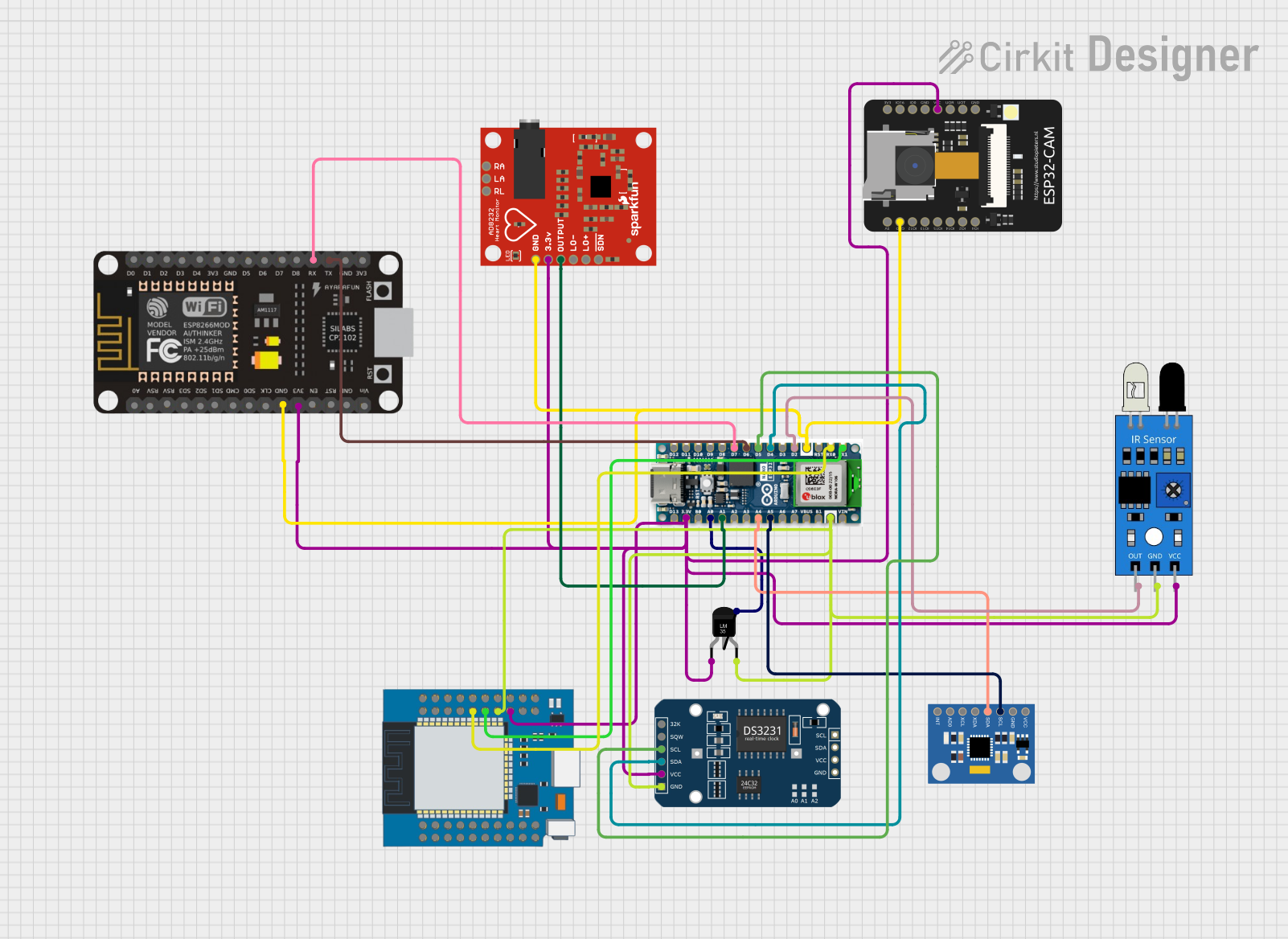
Circuit Documentation
Summary
The circuit in question is a multifunctional embedded system that integrates various sensors and microcontrollers to perform tasks such as heart rate monitoring, temperature sensing, motion detection, and real-time clock tracking. The primary microcontroller is an Arduino Nano ESP32, which interfaces with an ESP8266 NodeMCU, an AD8232 Heart Rate Monitor, an MPU6050 Accelerometer and Gyroscope, an IR sensor, a Temperature Sensor (LM35), an ESP32-CAM, an ESP32 Mini, and a DS3231 Real-Time Clock (RTC).
Component List
Arduino Nano ESP32
- Microcontroller with a variety of digital and analog pins, including I2C communication pins.
- Used as the main processing unit and communication hub for the sensors and modules.
ESP8266 NodeMCU
- Wi-Fi-enabled microcontroller with digital pins and a single analog input.
- Acts as a secondary controller and possibly for network connectivity.
AD8232 Heart Rate Monitor
- A module designed to measure heart rate through electrical signals.
- Interfaces with the Arduino Nano ESP32 for heart rate data acquisition.
MPU6050 Accelerometer + Gyroscope
- A motion tracking device that measures acceleration and rotational rates.
- Connected to the Arduino Nano ESP32 for motion sensing applications.
IR Sensor
- A simple infrared sensor for detecting proximity or object presence.
- Wired to the Arduino Nano ESP32 for digital input sensing.
Temperature Sensor (LM35)
- An analog temperature sensor that provides voltage output proportional to temperature.
- Connected to the Arduino Nano ESP32 for temperature measurements.
ESP32-CAM
- A small camera module with Wi-Fi capabilities, based on the ESP32.
- Can be used for image capture and possibly video streaming.
ESP32 Mini
- A compact version of the ESP32 microcontroller with various I/O capabilities.
- May serve as an additional processing unit or for specific I/O tasks.
DS3231 RTC
- A highly accurate I2C real-time clock module with a temperature-compensated crystal oscillator.
- Provides timekeeping functionality to the Arduino Nano ESP32.
Wiring Details
Arduino Nano ESP32
- D7 connected to ESP8266 NodeMCU RX
- D6 connected to ESP8266 NodeMCU TX
- D5 connected to DS3231 RTC SCL
- D4 connected to DS3231 RTC SDA
- D2 connected to IR Sensor out
- RX0 connected to ESP32 Mini GPIO17
- TX1 connected to ESP32 Mini GPIO16
- A0 connected to Temperature Sensor (LM35) Vout
- A1 connected to AD8232 Heart Rate Monitor OUTPUT
- A4 connected to MPU6050 SDA
- A5 connected to MPU6050 SCL
- 3.3V connected to ESP32-CAM VCC, ESP32 Mini VCC, AD8232 Heart Rate Monitor 3.3v, ESP8266 NodeMCU 3V3, IR Sensor vcc, DS3231 RTC VCC, Temperature Sensor (LM35) +Vs
- GND connected to ESP32-CAM GND, AD8232 Heart Rate Monitor GND, ESP8266 NodeMCU GND, ESP32 Mini GND, IR Sensor gnd, DS3231 RTC GND, Temperature Sensor (LM35) GND
ESP8266 NodeMCU
- RX connected to Arduino Nano ESP32 D7
- TX connected to Arduino Nano ESP32 D6
- 3V3 connected to common 3.3V net
- GND connected to common ground net
AD8232 Heart Rate Monitor
- 3.3v connected to common 3.3V net
- OUTPUT connected to Arduino Nano ESP32 A1
- GND connected to common ground net
MPU6050 Accelerometer + Gyroscope
- SDA connected to Arduino Nano ESP32 A4
- SCL connected to Arduino Nano ESP32 A5
- VCC not explicitly connected in the net list
- GND not explicitly connected in the net list
IR Sensor
- out connected to Arduino Nano ESP32 D2
- vcc connected to common 3.3V net
- gnd connected to common ground net
Temperature Sensor (LM35)
- +Vs connected to common 3.3V net
- Vout connected to Arduino Nano ESP32 A0
- GND connected to common ground net
ESP32-CAM
- VCC connected to common 3.3V net
- GND connected to common ground net
ESP32 Mini
- GPIO17 connected to Arduino Nano ESP32 RX0
- GPIO16 connected to Arduino Nano ESP32 TX1
- VCC connected to common 3.3V net
- GND connected to common ground net
DS3231 RTC
- SCL connected to Arduino Nano ESP32 D5
- SDA connected to Arduino Nano ESP32 D4
- VCC connected to common 3.3V net
- GND connected to common ground net
Documented Code
Arduino Nano ESP32 Code
#include <Wire.h>
#include <RTClib.h>
#include <Adafruit_MPU6050.h>
#include <Adafruit_Sensor.h>

#define IR_PIN 2 // Pin connected to the IR sensor

RTC_DS3231 rtc;
Adafruit_MPU6050 mpu;

void setup() {
  Serial.begin(115200);
  Wire.begin(); // Initialize I2C
  pinMode(IR_PIN, INPUT);

  // Initialize RTC
  if (!rtc.begin()) {
    Serial.println("Couldn't find RTC");
    while (1);
  }
  if (rtc.lostPower()) {
    Serial.println("RTC lost power, setting the time!");
    rtc.adjust(DateTime(F(__DATE__), F(__TIME__)));
  }

  // Initialize MPU6050
  if (!mpu.begin()) {
    Serial.println("Could not find a valid MPU6050 sensor, check wiring!");
    while (1);
  }
  mpu.setAccelerometerRange(MPU6050_RANGE_2_G);
  mpu.setGyroRange(MPU6050_RANGE_250_DEG);
  mpu.setFilterBandwidth(MPU6050_BAND_5_HZ);
}

void loop() {
  // Read the IR sensor
  int irValue = digitalRead(IR_PIN);
  Serial.print("IR Sensor Value: ");
  Serial.println(irValue);

  // Get current time from RTC
  DateTime now = rtc.now();
  Serial.print("Current Time: ");
  Serial.print(now.hour(), DEC);
  Serial.print(':');
  Serial.print(now.minute(), DEC);
  Serial.print(':');
  Serial.print(now.second(), DEC);
  Serial.println();

  // Read accelerometer and gyroscope data
  sensors_event_t a, g, temp;
  mpu.getEvent(&a, &g, &temp);

  Serial.print("Accel X: "); Serial.print(a.acceleration.x);
  Serial.print(", Y: "); Serial.print(a.acceleration.y);
  Serial.print(", Z: "); Serial.println(a.acceleration.z);

  Serial.print("Gyro X: "); Serial.print(g.gyro.x);
  Serial.print(", Y: "); Serial.print(g.gyro.y);
  Serial.print(", Z: "); Serial.println(g.gyro.z);

  delay(1000);
}
ESP8266 NodeMCU Code
#include <Wire.h>
#include <RTClib.h>

#define RX_PIN D5  // Pin for receiving data from Arduino

void setup() {
  Serial.begin(115200);
  Serial.println("NodeMCU Ready");
}

void loop() {
  if (Serial.available()) {
    String data = Serial.readStringUntil('\n'); // Read incoming data
    Serial.println("Received: " + data); // Print received data
  }

  // You can add additional functionality here, such as connecting to Wi-Fi, sending data to the cloud, etc.

  delay(1000);
}
(Note: The code for other microcontrollers is not included in this documentation as it was not provided in the input. If additional code is available for other microcontrollers, it should be documented in a similar fashion.)