
Circuit Documentation
Summary
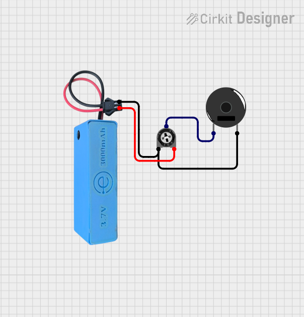
This document provides a detailed overview of a circuit consisting of a Trimmer Potentiometer, a Piezo Buzzer, and a MAHIR 1.mini power source. The circuit is designed to control the sound output of the Piezo Buzzer using the Trimmer Potentiometer to adjust the resistance.
Component List
Trimmer Potentiometer
- Description: A variable resistor used to adjust the resistance in the circuit.
- Pins: leg1, wiper, leg2
- Properties:
- Resistance: 10000 Ohms
Piezo Buzzer
- Description: An electronic device that produces sound when an electric signal is applied.
- Pins: pin 1, pin 2
MAHIR 1.mini
- Description: A power source providing 3.7V and GND connections.
- Pins: GND, 3.7v
Wiring Details
Trimmer Potentiometer
- leg1: Connected to GND of MAHIR 1.mini and pin 2 of Piezo Buzzer
- wiper: Connected to pin 1 of Piezo Buzzer
- leg2: Connected to 3.7v of MAHIR 1.mini
Piezo Buzzer
- pin 1: Connected to wiper of Trimmer Potentiometer
- pin 2: Connected to GND of MAHIR 1.mini and leg1 of Trimmer Potentiometer
MAHIR 1.mini
- GND: Connected to leg1 of Trimmer Potentiometer and pin 2 of Piezo Buzzer
- 3.7v: Connected to leg2 of Trimmer Potentiometer
Code
There is no embedded code associated with this circuit.
This documentation provides a comprehensive overview of the components and their connections within the circuit. The Trimmer Potentiometer allows for adjustable resistance, which in turn controls the sound output of the Piezo Buzzer, powered by the MAHIR 1.mini.