
Circuit Documentation
Summary
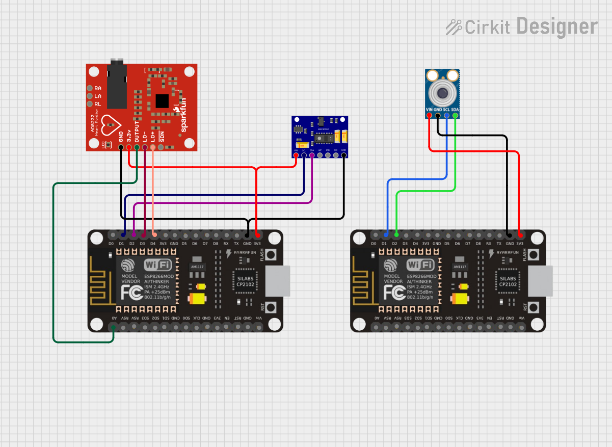
The circuit in question is designed to monitor heart rate and body temperature using a combination of sensors interfaced with ESP8266 NodeMCU microcontrollers. The MAX30102 sensor is used for heart rate and oxygen saturation measurement, while the AD8232 is a dedicated heart rate monitor, and the MLX90614 is an infrared thermometer for non-contact temperature measurement. The ESP8266 NodeMCU microcontrollers serve as the central processing units that read data from the sensors and can potentially transmit this data for further processing or display.
Component List
MAX30102 Heart Rate and Oxygen Sensor
- Description: A sensor for measuring heart rate and blood oxygen levels.
- Pins: VIN, SCL, SDA, INT, IRQ, RD, GND
ESP8266 NodeMCU
- Description: A Wi-Fi enabled microcontroller module with a wide range of GPIO pins.
- Pins: D0, D1, D2, D3, D4, 3V3, GND, D5, D6, D7, D8, RX, TX, A0, RSV, SD3, SD2, SD1, CMD, SD0, CLK, EN, RST, VIN
AD8232 Heart Rate Monitor
- Description: A single-lead heart rate monitor for wearable health monitoring.
- Pins: GND, 3.3v, OUTPUT, LO-, LO+, SDN, RA, LA, RL
MLX90614 Infrared Thermometer
- Description: An infrared thermometer for non-contact temperature measurements.
- Pins: SDA, SCL, GND, VIN
Wiring Details
MAX30102 Heart Rate and Oxygen Sensor
- VIN connected to 3V3 of ESP8266 NodeMCU
- SCL connected to D1 of ESP8266 NodeMCU
- SDA connected to D2 of ESP8266 NodeMCU
- GND connected to GND of ESP8266 NodeMCU
ESP8266 NodeMCU
- 3V3 supplies power to MAX30102, AD8232, and MLX90614 sensors
- GND is common for all components
- D1 (SCL) and D2 (SDA) are used for I2C communication with MAX30102 and MLX90614
- D3 and D4 are connected to LO- and LO+ of the AD8232
- A0 is connected to the OUTPUT of the AD8232
AD8232 Heart Rate Monitor
- 3.3v connected to 3V3 of ESP8266 NodeMCU
- OUTPUT connected to A0 of ESP8266 NodeMCU
- LO- connected to D3 of ESP8266 NodeMCU
- LO+ connected to D4 of ESP8266 NodeMCU
- GND connected to GND of ESP8266 NodeMCU
MLX90614 Infrared Thermometer
- VIN connected to 3V3 of ESP8266 NodeMCU
- SCL connected to D1 of ESP8266 NodeMCU
- SDA connected to D2 of ESP8266 NodeMCU
- GND connected to GND of ESP8266 NodeMCU
Documented Code
No code has been provided for the microcontrollers. To fully utilize the circuit, embedded code should be written and uploaded to the ESP8266 NodeMCU microcontrollers. The code should initialize and read data from the sensors via the I2C interface, process the data as required, and handle any communication or output display tasks.