
ESP32-Based Smart Home Automation System with Motion Detection and Manual Control
View and Edit Project In Cirkit Designer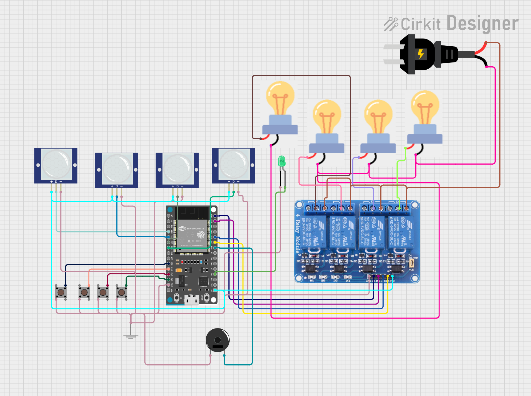
Circuit Documentation
Summary
The circuit is designed to control a set of bulbs using relays, which are in turn controlled by an ESP32 Devkit V1 microcontroller. The ESP32 reads inputs from pushbuttons and PIR motion sensors to determine the state of the relays. The relays can switch AC power to the bulbs, allowing them to be turned on or off. The circuit also includes a green LED and a piezo buzzer for status indication.
Component List
Microcontroller
- ESP32 Devkit V1: A microcontroller with WiFi and Bluetooth capabilities, used as the central controller for the circuit.
Sensors
- PIR Motion Sensors: Used to detect motion within the environment.
- Pushbuttons: Provide a manual interface for the user to interact with the circuit.
Actuators
- Relay 4 Channel 5v: Allows the ESP32 to control higher power devices such as bulbs.
- LED (Green): Acts as a visual indicator.
- Piezo Buzzer: Provides audible feedback or alerts.
Power Sources
- AC Source: Supplies power to the bulbs through the relays.
- GND: Common ground reference for the circuit.
Output Devices
- Bulbs: The primary output devices that are controlled by the relays.
Wiring Details
ESP32 Devkit V1
3V3connected to Relay VCC, PIR Motion Sensors VCC.GNDconnected to GND of all components.D2connected to LED anode.D18connected to Piezo Buzzer pin 2.D19,D21,D22,D23connected to Relay IN4, IN3, IN2, IN1 respectively.D34,D35,D32,D33connected to PIR Motion Sensors OUT.D27,D14,D12,D13connected to Pushbuttons Pin 3 (out).
Relay 4 Channel 5v
VCCconnected to ESP32 3V3.GNDconnected to common GND.IN1,IN2,IN3,IN4connected to ESP32 D23, D22, D21, D19 respectively.COM1,COM2,COM3,COM4connected to respective bulbs power.NO1,NO2,NO3,NO4connected to AC source +.
Pushbuttons
Pin 3 (out)connected to ESP32 D27, D14, D12, D13.Pin 2 (in)connected to common GND.
PIR Motion Sensors
VCCconnected to ESP32 3V3.OUTconnected to ESP32 D34, D35, D32, D33.GNDconnected to common GND.
LED (Green)
Anodeconnected to ESP32 D2.Cathodeconnected to common GND.
Piezo Buzzer
Pin 2connected to ESP32 D18.Pin 1connected to common GND.
Bulbs
Powerconnected to respective Relay COM.GNDconnected to AC source -.
AC Source
+connected to Relay NO1, NO2, NO3, NO4.-connected to Bulbs GND.
Documented Code
No code was provided for the microcontroller. The documentation of the code would include the setup of the GPIO pins, the main loop with the logic for reading sensor inputs and controlling the relay outputs, and any interrupt service routines or functions for debouncing the pushbuttons or reading the PIR sensors. Since no code is available, this section cannot be completed.