
Multi-Sensor Monitoring System with INA219, Hall Sensor, and OLED Display
View and Edit Project In Cirkit Designer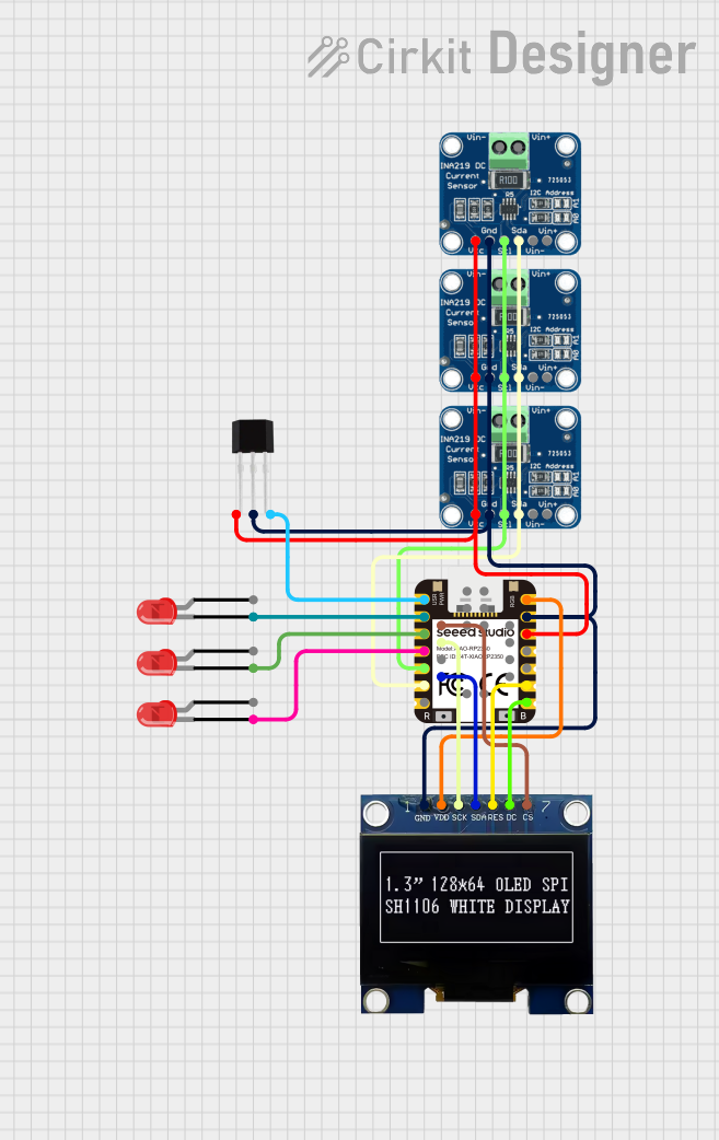
Circuit Documentation
Summary
This document provides a detailed overview of a circuit design that includes various components such as current sensors, LEDs, a hall sensor, a microcontroller, and an OLED display. The circuit is designed to measure current, detect magnetic fields, and display information on an OLED screen. The microcontroller serves as the central unit, interfacing with all other components.
Component List
INA219
- Description: Current sensor
- Pins: VCC, GND, SCL, SDA, VIN -, VIN +
LED: Two Pin (red)
- Description: Red LED
- Pins: Cathode, Anode
GH1248 Hall Sensor
- Description: Hall effect sensor
- Pins: VCC, GND, Signal
Seeed Studio RP2350
- Description: Microcontroller
- Pins: D0, D1, D2, D3, D4, D5, D6, VBus, GND, 3.3V, D10, D9, D8, D7, D11, D12, D13, D14, Batt+, Batt-, D15, D16, D17, D18, DIO, CLK, RST, BOOT
SSD1306 128x64 SPI OLED
- Description: OLED display
- Pins: GND, Vcc, SCLK, MOSI, Reset, DC, CS
Wiring Details
INA219 (Current Sensor)
- VCC: Connected to 3.3V of Seeed Studio RP2350
- GND: Connected to GND of Seeed Studio RP2350
- SCL: Connected to D4 of Seeed Studio RP2350
- SDA: Connected to D5 of Seeed Studio RP2350
LED: Two Pin (red) (Instance 1)
- Cathode: Connected to D3 of Seeed Studio RP2350
- Anode: Not connected (assumed to be connected to a current-limiting resistor and then to VCC)
LED: Two Pin (red) (Instance 2)
- Cathode: Connected to D1 of Seeed Studio RP2350
- Anode: Not connected (assumed to be connected to a current-limiting resistor and then to VCC)
LED: Two Pin (red) (Instance 3)
- Cathode: Connected to D2 of Seeed Studio RP2350
- Anode: Not connected (assumed to be connected to a current-limiting resistor and then to VCC)
GH1248 Hall Sensor
- VCC: Connected to 3.3V of Seeed Studio RP2350
- GND: Connected to GND of Seeed Studio RP2350
- Signal: Connected to D0 of Seeed Studio RP2350
Seeed Studio RP2350 (Microcontroller)
- 3.3V: Connected to VCC of INA219 and GH1248 Hall Sensor
- GND: Connected to GND of INA219, GH1248 Hall Sensor, and SSD1306 OLED
- D0: Connected to Signal of GH1248 Hall Sensor
- D1: Connected to Cathode of LED (Instance 2)
- D2: Connected to Cathode of LED (Instance 3)
- D3: Connected to Cathode of LED (Instance 1)
- D4: Connected to SCL of INA219
- D5: Connected to SDA of INA219
- VBus: Connected to Vcc of SSD1306 OLED
- D8: Connected to Reset of SSD1306 OLED
- D7: Connected to DC of SSD1306 OLED
- D15: Connected to MOSI of SSD1306 OLED
- D17: Connected to SCLK of SSD1306 OLED
- D18: Connected to CS of SSD1306 OLED
SSD1306 128x64 SPI OLED
- GND: Connected to GND of Seeed Studio RP2350
- Vcc: Connected to VBus of Seeed Studio RP2350
- SCLK: Connected to D17 of Seeed Studio RP2350
- MOSI: Connected to D15 of Seeed Studio RP2350
- Reset: Connected to D8 of Seeed Studio RP2350
- DC: Connected to D7 of Seeed Studio RP2350
- CS: Connected to D18 of Seeed Studio RP2350
Code
No code is provided for this circuit.
This document provides a comprehensive overview of the circuit, including a summary, component list, wiring details, and code documentation. Each component is described, and its connections are detailed to ensure clarity and ease of understanding.