
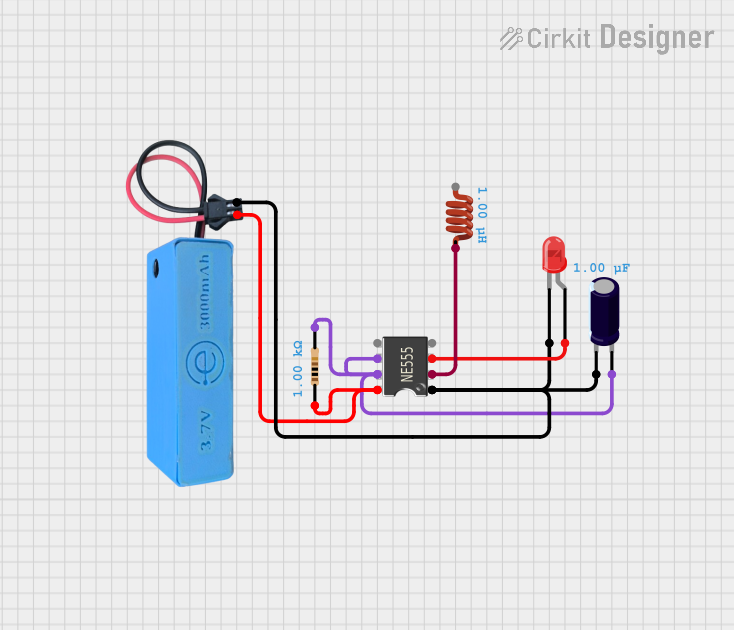
Circuit Documentation
Summary
This document provides a detailed description of a circuit that includes a 555 Timer IC, a resistor, a red LED, an electrolytic capacitor, an inductor, and a power supply module (MAHIR 1.mini). The circuit is designed to utilize the 555 Timer IC in an astable configuration to drive the LED. The power supply is provided by the MAHIR 1.mini module.
Component List
555 Timer IC
- Pins: VCC+, Dis, Th, CV, Rst, Out, Trig, GND
- Description: A versatile timer IC used for generating precise time delays or oscillation.
- Purpose in Circuit: Used in astable mode to generate a square wave signal.
Resistor
- Pins: pin1, pin2
- Description: A passive electrical component that provides resistance to the flow of current.
- Properties:
- Resistance: 1000 Ohms
- Purpose in Circuit: Used to set the timing interval of the 555 Timer IC.
LED: Two Pin (red)
- Pins: cathode, anode
- Description: A light-emitting diode that emits red light when current flows through it.
- Purpose in Circuit: Indicates the output state of the 555 Timer IC.
Electrolytic Capacitor
- Pins: -, +
- Description: A polarized capacitor with a high capacitance value.
- Properties:
- Capacitance: 0.000001 Farads
- Purpose in Circuit: Used to stabilize the voltage and set the timing interval of the 555 Timer IC.
MAHIR 1.mini
- Pins: GND, 3.7v
- Description: A power supply module.
- Purpose in Circuit: Provides the necessary power to the circuit.
Inductor
- Pins: pin 0, pin 1
- Description: A passive electrical component that stores energy in a magnetic field.
- Properties:
- Inductance: 0.000001 Henrys
- Purpose in Circuit: Used to filter the signal and stabilize the circuit.
Wiring Details
555 Timer IC
VCC+ is connected to:
- 3.7v of MAHIR 1.mini
- pin1 of Resistor
Dis is connected to:
- Th of 555 Timer IC
- pin2 of Resistor
- + of Electrolytic Capacitor
Out is connected to:
- anode of LED: Two Pin (red)
Trig is connected to:
- pin 1 of Inductor
GND is connected to:
- GND of MAHIR 1.mini
- cathode of LED: Two Pin (red)
- - of Electrolytic Capacitor
Resistor
pin1 is connected to:
- VCC+ of 555 Timer IC
- 3.7v of MAHIR 1.mini
pin2 is connected to:
- Dis of 555 Timer IC
- Th of 555 Timer IC
- + of Electrolytic Capacitor
LED: Two Pin (red)
anode is connected to:
- Out of 555 Timer IC
cathode is connected to:
- GND of 555 Timer IC
- GND of MAHIR 1.mini
- - of Electrolytic Capacitor
Electrolytic Capacitor
+ is connected to:
- pin2 of Resistor
- Dis of 555 Timer IC
- Th of 555 Timer IC
- is connected to:
- GND of 555 Timer IC
- GND of MAHIR 1.mini
- cathode of LED: Two Pin (red)
MAHIR 1.mini
3.7v is connected to:
- VCC+ of 555 Timer IC
- pin1 of Resistor
GND is connected to:
- GND of 555 Timer IC
- cathode of LED: Two Pin (red)
- - of Electrolytic Capacitor
Inductor
- pin 1 is connected to:
- Trig of 555 Timer IC
Code
There is no code provided for this circuit.
This document provides a comprehensive overview of the circuit, including the components used, their connections, and their roles within the circuit.